Control and Display Elements
52
Pos: 30.4 /Überschri ften/Zwischenüber schriften/A-E/ Bei Ausführung elektrisc he Kreiselhöhenverst ellung @ 361\mod_1439 473827228_78.doc x @ 2668838 @ @ 1
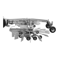
With electrical rotor height adjustment version
Pos: 30.5 /BA/Maschi nenbeschreibung/Sc hwader/elektrisc h-hydraulische Ei nkreiselaushebung Sei tenschwader_Bild @ 375\ mod_14428211051 41_78.docx @ 2726805 @ @ 1
3
5
1
2
TS620-004_1
4
Fig. 17
Pos: 30.6 /BA/Maschi nenbeschreibung/Sc hwaderelektrisc h-hydraulische Einkr eiselaushebung_Sei tenschwader_Tabe lle @ 359\mod_14391951 08968_78.docx @ 2661625 @ @ 1
The following table explains the function of the individual switches.
Switch Function
1) Warning light (red) Lit when operation panel is switched on.
2) Main switch Switch operation panel on (1) and off (0).
3) Toggle switch (inching) Set the working height on right rotor.
4) Digital display
Minimum distance to the ground = 0 – 99 = maximum
distance to the ground.
5) Toggle switch (inching) Set the working height on left rotor.
Pos: 31 /Layout Module /---------------Seitenumbruch---------------- @ 0\mod_1196175311226_0.docx @ 4165 @ @ 1
 Loading...