Settings
94
Pos: 40.6.5.1 /Übersc hriften/Übersc hriften 3/A-E/BBei Ausführung "Nachlaufend e Tasträder" @ 427\mod_14 55009765507_78.doc x @ 2957230 @ 3 @ 1
11.1.2 For the “Trailing Guide Wheels” Version
Pos: 40.6.5.2 /BA/ Einstellungen/Sch wader/Kreiselfahrwer k/Kreiselfahr werk Bild nachlaufendes Rad S wadro TC 680_TC 760_TS 620_TS 680 @ 247\ mod_1396423997182_78. docx @ 1925374 @ @ 1
I
I
I
SW700091_1
3
1
2
III
Fig. 54
Pos: 40.6.5.3 /Lay out Module /-------- --------Leerzei le 5 Pt.-------------------- @ 120\mod_1342592918145_0.docx @ 1092566 @ @ 1
Pos: 40.6.5.4 /BA/ Einstellungen/Sch wader/Kreiselfahrwer k/Kreiselfahr werk Längsneigung_nach laufendes Rad_Mittel- und Seitenschwade r @ 247\mod_1396366697765_ 78.docx @ 1924247 @ @ 1
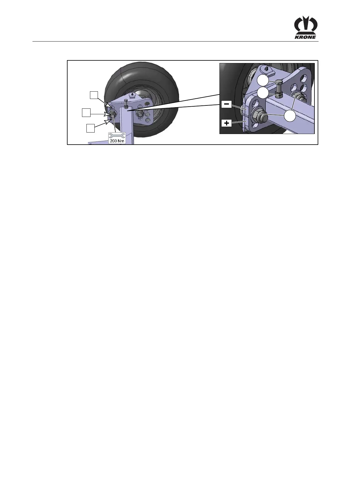
Longitudinal inclination:
The longitudinal inclination can be changed (rotor tips forward) by reconnecting the rear guide
wheels (right and left) of the chassis in positions I, II and III.
Pos: 40.6.5.5 /Lay out Module /-------- --------Leerzei le 5 Pt.-------------------- @ 120\mod_1342592918145_0.docx @ 1092566 @ @ 1
Pos: 40.6.5.6 /BA/ Einstellungen/Sch wader/Kreiselfahrwer kKreiselneigung ei nstellen Text Positi on_äußeres Tandemfahr werk @ 466\mod_146797007 5772_78.docx @ 3140777 @ @ 1
Pos. I = reduce rotor inclination
Pos. II = increase rotor inclination
Pos: 40.6.5.7 /BA/ Einstellungen/Sch wader/Kreiselfahrwer kKreiselfahrwer k Vorgehensweise Swadr o diverse TC und TS @ 427\mod_1455 032842030_78.doc x @ 2959284 @ @ 1
Do not step under the raised rotors.
• Only raise the outrigger arms as far as necessary to perform the changeover work.
• To set rotor inclination, dismount the rear guide wheels and move them in the hole pattern.
For better orientation, observe the basic setting of rotor inclination, refer to chapter Initial
Operation, “Rotor Inclination - Basic Setting”.
Pos: 40.6.5.8 /BA/ Einstellungen/Sch wader/Kreiselfahrwer k/Kreiselfahr werk Querneigung_TS 620 (Twin) _TS 680 (Twin)_TS 740 ( Twin) @ 247\mod_13963663 00182_78.docx @ 1924218 @ @ 1
Transverse inclination:
A change of the transverse inclination (to the direction of travel) is reached if one of the rear
guide wheels is set higher or deeper compared to the other guide wheel.
Pos: 40.6.5.9 /Lay out Module /-------- --------Leerzei le-------------------- @ 240\mod_1395147357027 _0.docx @ 1890988 @ @ 1
Pos: 40.6.5.10 /BA/ Einstellungen/Sc hwader/Kreiselfahr werkKreiselfahr werk Vorgehensweise Swadr o diverse TC und TS @ 427\mod_145 5032842030_78.doc x @ 2959284 @ @ 1
Do not step under the raised rotors.
• Only raise the outrigger arms as far as necessary to perform the changeover work.
• To set rotor inclination, dismount the rear guide wheels and move them in the hole pattern.
For better orientation, observe the basic setting of rotor inclination, refer to chapter Initial
Operation, “Rotor Inclination - Basic Setting”.
Pos: 40.6.5.11 /Layout Module /---------------Seitenumbruch---------------- @ 0\mod_1196175311226_0.doc x @ 4165 @ @ 1
 Loading...