Settings
92
Pos: 40.6.1 /Überschr iften/Überschr iften 2/K-O/KKreisel neigung einstellen @ 191\ mod_1381819931154 _78.docx @ 1631074 @ 2 @ 1
11.1 Setting the Rotor Inclination
Pos: 40.6.2 /BA/Si cherheit/6. Überar beitete Warnhinweise/W arnung- Einstellarb eiten Maschinen @ 297\mod_14 12757509120_78.doc x @ 2333197 @ @ 1
WARNING!
When performing repair, maintenance or cleaning work on the machine, or in case of
technical intervention, drive elements may start moving. Thus there is a risk of serious
injuries or death.
• Switch off tractor engine, remove the ignition key and carry it with you.
• Secure the tractor against accidental start-up and against rolling.
• Wait until all machine parts have come to a complete stop and have been cooled down
completely.
Pos: 40.6.3 /BA/Ei nstellungen/Schwader /Kreiselfahrwerk/ Kreiselneigung ei nstellen Text Einlei tung Swadro TC 680_TC 760 @ 223\mod_1 392114706229_78.doc x @ 1808993 @ @ 1
The rotor pitch angle has been set at a transverse angle to the chassis in the factory. If the
crops are not picked up properly, the working quality can be improved by adjusting the rotor
pitch.
The rotor pitch angle is adjusted for each rotor via the guide wheels at the chassis. The best
results are achieved if the rotor pitch adjustment ensures the tines are closer to the ground level
when outputting the crops than at the start when picking up the crops.
Pos: 40.6.4.1 /Übersc hriften/Übersc hriften 3/K-O/KKrei selfahrwerk (Serie) @ 223\mod_1392126168498_78. docx @ 1810305 @ 3 @ 1
11.1.1 Rotor chassis (serial)
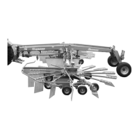
Pos: 40.6.4.2 /BA/ Einstellungen/Sch wader/Kreiselfahrwer k/Kreiselfahr werk Bild Swadro TC 680_TC 760_ TS 620_ TS 680 @ 247\mod_13964240740 75_78.docx @ 1925403 @ @ 1
SW700077_2
I
II
+
1
Fig. 53
Pos: 40.6.4.3 /Lay out Module /-------- --------Leerzei le 5 Pt.-------------------- @ 120\mod_1342592918145_0.docx @ 1092566 @ @ 1
Pos: 40.6.4.4 /BA/ Einstellungen/Sch wader/Kreiselfahrwer k/Kreiselfahr werk Längsneigung_Krei selfahrwerk (Ser ie) und Tandemfahrwerk_ Mittel- und Seitensc hwader @ 247\mod_139642081 3830_78.docx @ 1925162 @ @ 1
Longitudinal inclination:
A change of longitudinal inclination (rotor tilts to the front) is reached if the rear guide wheels
(right and left) of the chassis are reconnected in one of the seven bore holes in the hole pattern.
Pos: 40.6.4.5 /Lay out Module /-------- --------Leerzei le 5 Pt.-------------------- @ 120\mod_1342592918145_0.docx @ 1092566 @ @ 1
Pos: 40.6.4.6 /BA/ Einstellungen/Sch wader/Kreiselfahrwer kKreiselneigung ei nstellen Text Positi on_äußeres Tandemfahr werk @ 466\mod_146797007 5772_78.docx @ 3140777 @ @ 1
Pos. I = reduce rotor inclination
Pos. II = increase rotor inclination
Pos: 40.6.4.7 /BA/ Einstellungen/Sch wader/Kreiselfahrwer kKreiselfahrwer k Vorgehensweise Swadr o diverse TC und TS @ 427\mod_1455 032842030_78.doc x @ 2959284 @ @ 1
Do not step under the raised rotors.
• Only raise the outrigger arms as far as necessary to perform the changeover work.
• To set rotor inclination, dismount the rear guide wheels and move them in the hole pattern.
For better orientation, observe the basic setting of rotor inclination, refer to chapter Initial
Operation, “Rotor Inclination - Basic Setting”.
Pos: 40.6.4.8 /Layout Module /---------------Seitenumbruch---------------- @ 0\mod_1196175311226_0.docx @ 4165 @ @ 1
 Loading...