emergency power-off function is activated.
NOTE For Europe, the emergency switch requirements are detailed in Harmonized
document HD-384-48 S1, “Electrical Installation of the Buildings, Part 4: Protection
for Safety Chapter 46: Isolation and Switching.”
NOTE Leave the EPO connector installed onto the EPO port of the UPS even
if the EPO function is not needed.
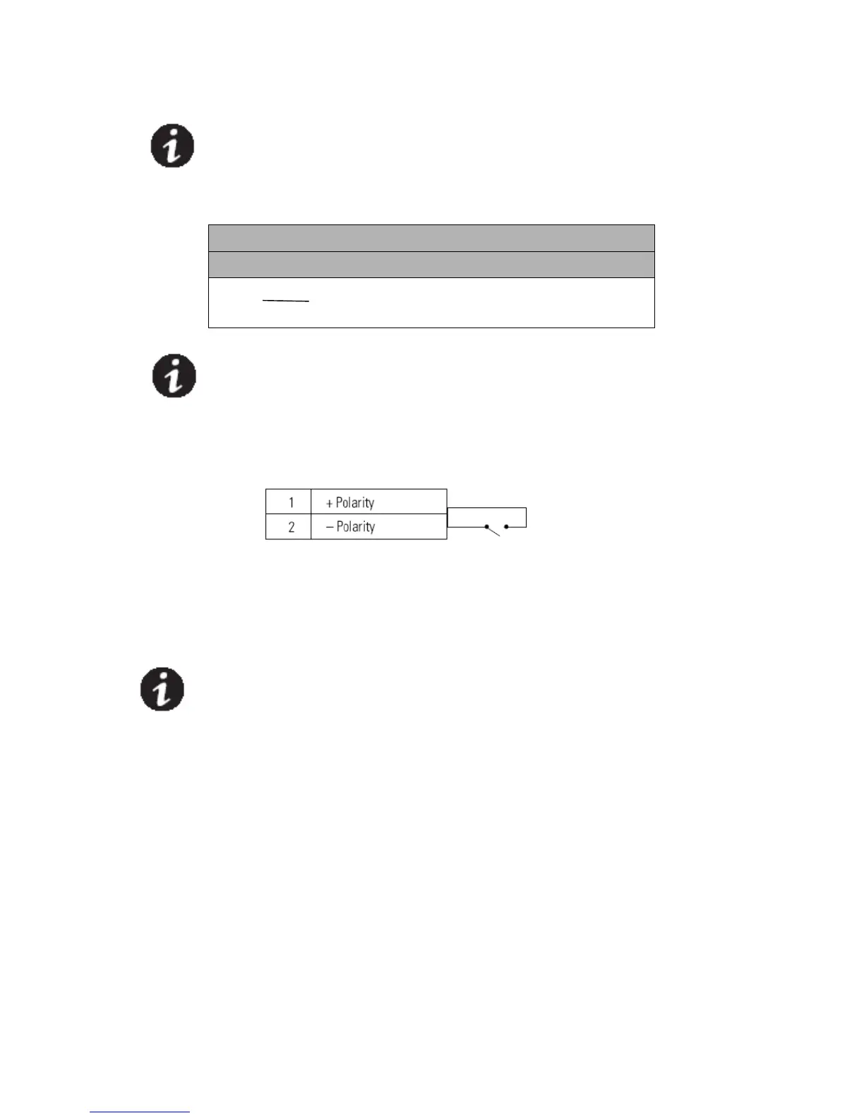
0TSee Figure 17, 18 on page 35 for EPO location. Figure 21 shows a schematic of
the EPO connector contacts.
0T Figure 21 0TEPO Connections
0TYou can set the EPO polarity. See the “EPO Input Polarity” setting in “User
Settings” on page 29.
0TNOTE Depending on user configuration, the pins must be shorted or opened to keep
the UPS running. To restart the UPS, reconnect (re-open) the EPO connector pins and
turn on the UPS manually. Maximum resistance in the shorted loop is 10 ohm.
0TNOTE Always test the EPO function before applying your critical load to avoid
accidental load loss.
Load Segments
0TLoad segments are sets of receptacles that can be controlled by power
management software or through the display, providing an orderly shutdown and
startup of your equipment. For example, during a power outage, you can keep
critical equipment running while you turn off other equipment. This feature allows
you to save battery power.
0T Each UPS has two load segments:
0T● Load Segment 1: The power shedding battery voltage of this segment can be set
by LCD.
0T● Load Segment 2.
0TSee “Rear Covers” on page 49 for load segments for each UPS model.
 Loading...