24 IGNITION SYSTEM 206
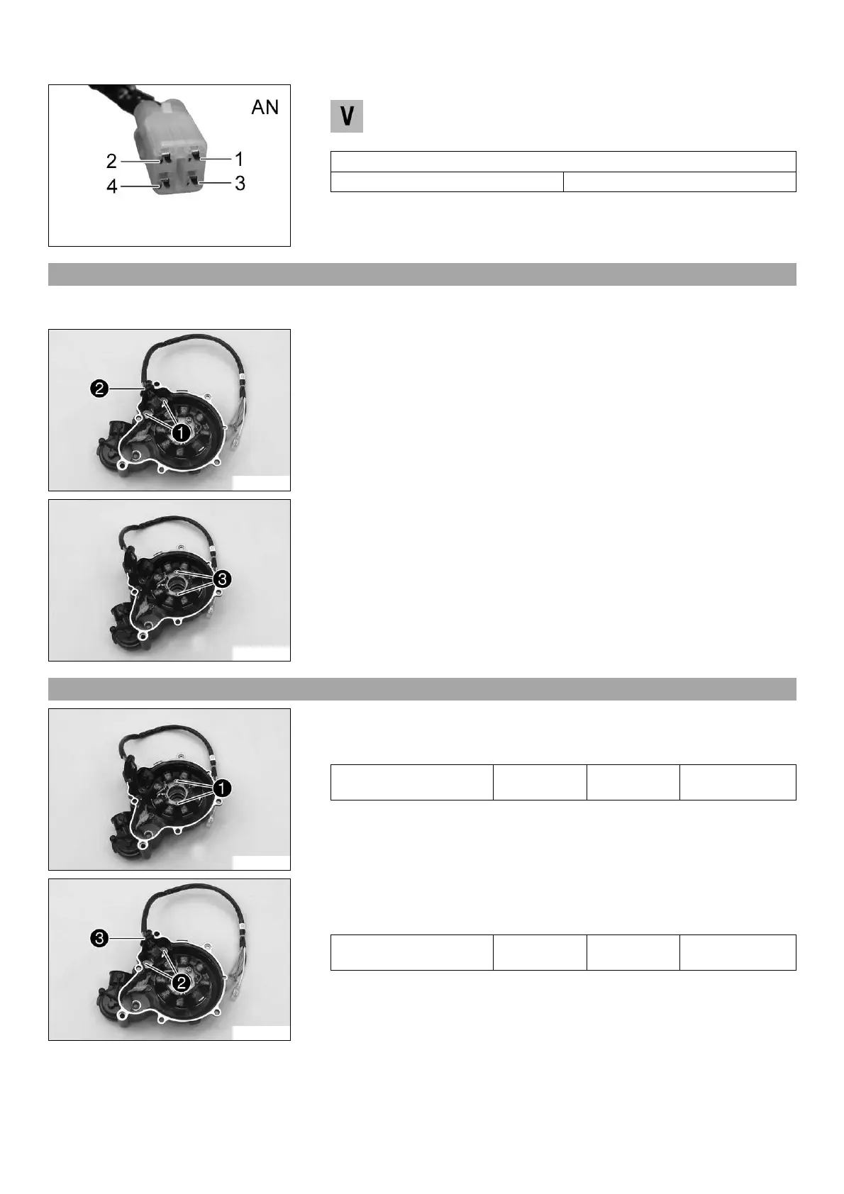
601213-10
Check the ignition pulse generator voltage
– Measure the voltage between the specified points.
Alternator, charging coil/ignition pulse generator, connector AN pin 3 –
Alternator, charging coil/ignition pulse generator, connector AN pin 4
Crankshaft position sensor
Voltage 2… 4 V
» The specifications have not been met:
– Change the ignition pulse generator.
24.9 Removing the stator and crankshaft position sensor
Condition
The alternator cover has been removed.
303441-10
– Remove screw
1
.
– Remove cable support sleeve
2
from the alternator cover.
303442-10
– Remove screw
3
.
– Remove the stator and crankshaft position sensor from the alternator cover.
24.10 Installing the stator and crankshaft position sensor
303442-11
– Position the stator in the alternator cover.
– Mount and tighten screws
1
.
Guideline
Screw, stator M6 8 Nm
(5.9 lbf ft)
Loctite
®
243™
303441-11
– Position the crankshaft position sensor.
– Mount and tighten screws
2
.
Guideline
Screw, crankshaft position
sensor
M5 6 Nm
(4.4 lbf ft)
Loctite
®
243™
– Position cable support sleeve
3
in the alternator cover.

 Loading...