2WA/2NJ/2RK
4-108
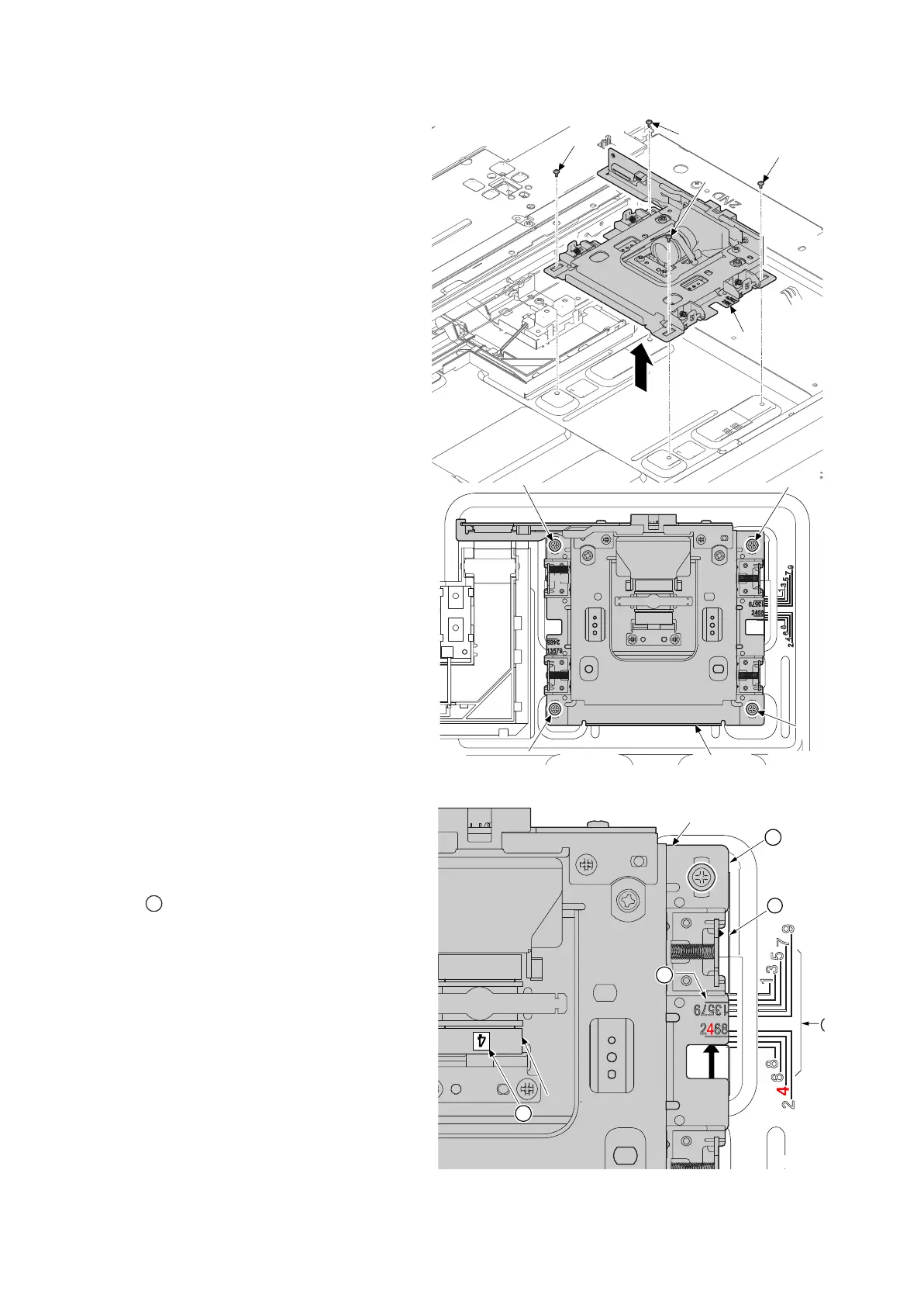
8. Remove four screws (a)(M3x8).
9. Detaches the lens unit (b) in the direc-
tion of the arrow.
Figure 4-159
Detaching the lens unit
Decide the fix position of lens unit (a) by the
following.
The right and left of machine: Confirm the
number on the label affixed on the lens (b).
Match the line (c) of lens unit (a) to the posi-
tioning line (b) of same number on frame side.
The rear and front of machine: Match the edge
(e) of lens unit (a) to the positioning line (d) on
frame side.
Fix the lens unit (a) as before with four screws.
Figure 4-160
a
a
a
a
b
a
a
a
a
b
14j0254
 Loading...