EasyManua.ls Logo

Kyocera TASKalfa 420i - Service Manual

Kyocera TASKalfa 420i
508 pages
Print Icon
To Next Page IconTo Next Page
Loading...
SERVICE
MANUAL
Published in May 2010
842KS113
2KSSM063
Rev. 3
TASKalfa 420i
TASKalfa 520i

Table of Contents

Other manuals for Kyocera TASKalfa 420i

Questions and Answers

  • E
    Eric ClineNov 21, 2025
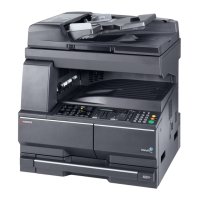
    What to do if Kyocera TASKalfa 420i network connection fails?
    • C
      Cathy HallNov 21, 2025
      If a network connection fails, for example, indicated by a Send Error, try the following: * Connect the network cable and properly set up TCP/IP. * Check folder sharing and access permissions in the Folder Properties dialog box. * Enable the SMB protocol setting. * Verify the host name of the destination computer and the name of the shared folder. * Confirm the domain name and domain user name are correct. * Ensure the login password is correct. * If the domain name specified in [Host Name] differs from the one specified in [Login User Name], delete the domain name and a \\ from the name entered in [Login User Name]. * Also, ensure the time setting is the same between the machine, PC, and the domain server. * To configure Windows Firewall, open Control Panel from the Sta...
  • K
    Kayla PorterAug 25, 2025
    Why Kyocera TASKalfa 420i cannot send document?
    • C
      Chad RobertsAug 26, 2025
      If your Kyocera All in One Printer cannot send a document, make sure the modular cord is correctly connected. If a send error is displayed, identify the cause of the error and try sending again. Also, verify whether TX (transmission) restriction is activated and, if so, cancel the TX restriction.
  • J
    Jeffrey ThompsonAug 26, 2025
    Why Kyocera All in One Printer cannot receive document?
    • D
      David FrenchAug 27, 2025
      If your Kyocera All in One Printer cannot receive a document, first check that the modular cord is correctly connected. If a communication error is displayed, address the cause of the error and ask the sender to retry. Additionally, check if RX (reception) restriction is activated and, if it is, cancel the RX restriction.
  • S
    Shelby ArellanoAug 27, 2025
    Why Kyocera All in One Printer has no print output after reception?
    • M
      Matthew WestAug 27, 2025
      If there is no print output after reception on your Kyocera All in One Printer, check if memory forwarding is activated and verify the forwarding destination.
  • R
    robertnovakAug 28, 2025
    What to do if Kyocera All in One Printer says to add paper?
    • G
      gabriellecarterAug 28, 2025
      If your Kyocera All in One Printer displays this message, it means the indicated cassette or MP tray is out of paper. Add paper of the same size as indicated. If a specific type of printing paper is specified, the necessary paper types will also be displayed. To use a different paper source, select the desired paper source and press [Continue]. You can also press [MP Tray Setting] to change the paper size/type of the MP tray. Also, make sure that the cassette is securely loaded; remove it and reload it completely.
  • J
    jameslynchSep 15, 2025
    Why Kyocera TASKalfa 420i All in One Printer cannot use polling reception?
    • T
      ttannerSep 15, 2025
      If your Kyocera All in One Printer cannot use polling reception, check with the recipient to ensure that polling transmission is being used correctly on the sending machine.
  • R
    robertreevesSep 12, 2025
    Why Kyocera All in One Printer cannot store memory forwarding data in a FAX Box?
    • L
      lindsay87Sep 12, 2025
      If your Kyocera All in One Printer cannot store memory forwarding data in a FAX Box, verify that the FAX Box is specified correctly in the memory forwarding setting. Also, ensure there is free space available in the memory.
  • M
    michael89Sep 13, 2025
    Why Kyocera TASKalfa 420i All in One Printer cannot output from a FAX Box?
    • C
      Charlene WestSep 13, 2025
      If your Kyocera All in One Printer cannot output from a FAX Box, make sure you enter the correct box password if one has been set.
  • J
    Jorge McdanielSep 5, 2025
    Why Kyocera TASKalfa 420i cannot perform memory forwarding?
    • S
      Steven CookSep 5, 2025
      If your Kyocera All in One Printer cannot perform memory forwarding, check whether memory forwarding is set to [On] in the settings.
  • A
    Amy EspinozaSep 3, 2025
    Why Kyocera All in One Printer cannot perform broadcast transmission?
    • G
      Gary RoseSep 3, 2025
      If your Kyocera All in One Printer cannot perform broadcast transmission, it's likely because there isn't enough free space in the memory. Try again after freeing up memory, or create free space in the memory.

Summary

Safety Precautions

Safety Warnings and Precautions

Safety Symbols

Explains various safety symbols used for warnings and precautions.

1. Installation Precautions

2. Precautions for Maintenance

1-1 Specifications

Machine Specifications

Details on machine type, printing method, supported originals, paper weight/type/size, speeds, and warm-up time.

1-1-2 Parts names

Machine Parts Identification

Identifies and labels the main external components of the machine.

Operation Panel Components

Identifies and labels all keys and indicators on the machine's operation panel.

1-1-3 Machine cross section

1-2 Installation

Installation Environment Requirements

Specifies environmental conditions like temperature, humidity, power supply, and location.

1-2-2 Unpacking and installation

Installation Procedure

Details the step-by-step process for unpacking and installing the machine.

1-3 Maintenance Mode

Executing a Maintenance Item

Describes the process for entering and running specific maintenance functions.

Maintenance Modes Item List

Lists all available maintenance items with their numbers, content, and initial settings.

U003 Setting the service telephone number

U004 Displaying the machine number

U019 Displaying the ROM version

U021 Initializing counters and mode settings

U024 HDD formatting

U030 Checking motor operation

U031 Checking switches for paper conveying

U032 Checking clutch operation

U033 Checking solenoid operation

U034 Adjusting the print start timing

Center Line Adjustment

Details on how to adjust the center line for copy images.

U035 Setting the printing area for folio paper

U037 Checking the operation of the fan motors

U051 Adjusting the deflection in the paper

U053 Setting the adjustment of the motor speed

U059 Setting fan mode

U061 Turning the exposure lamp on

U063 Adjusting the shading position

U065 Adjusting the scanner magnification

Main Scanning Direction Adjustment

Details on adjusting scanner magnification for the main scanning direction.

Auxiliary Scanning Direction Adjustment

Details on adjusting scanner magnification for the auxiliary scanning direction.

U066 Adjusting the scanner leading edge registration

U067 Adjusting the scanner center line

U068 Adjusting the scanning position for originals from the DP

U070 Adjusting the DP magnification

U071 Adjusting the DP scanning timing

Leading Edge Registration Adjustment

Details on adjusting leading edge registration for DP scanning.

U073 Checking scanner operation

U074 Adjusting the DP input light luminosity

U080 Setting the economy mode

U081 Adjusting the correct exposure

U087 Setting DP reading position modification operation

U089 Outputting a MIP-PG pattern

U091 Setting the white line correction

U093 Setting the exposure density gradient

U099 Adjusting original size detection

U100 Setting the main high voltage

U101 Setting the other high voltages

U102 Setting the cleaning interval for the main charger

U109 Displaying the drum type

U110 Checking the drum count

U111 Checking the drum drive time

U112 Setting toner refresh operation

U114 Setting separation charger mode

U117 Checking the drum number

U118 Displaying the drum history

U127 Checking the transfer count

U130 Initial setting for the developing unit

U136 Setting toner near end mode

U139 Displaying the temperature and humidity

U144 Setting toner disposal operation

U155 Checking sensors for toner

U157 Checking the developing drive time

U158 Checking the developing count

U161 Setting the fuser control temperature

U163 Resetting the fuser problem data

U167 Checking;clearing the fuser counts

U196 Turning the fuser heater on

U198 Setting the fuser phase control

U199 Checking the fuser temperature

U200 Turning all LEDs on

U201 Initializing the touch panel

U202 Setting the KMAS host monitoring system

U203 Checking DP operation

U204 Setting the presence or absence of a key card or key counter

U206 Setting the presence or absence of the coin vender

U207 Checking the operation panel keys

U208 Setting the paper size for the paper feeder

U221 Setting the USB host lock function

U222 Setting the IC card type

U223 Operation panel lock

U224 Panel sheet extension

U234 Setting punch destination

U236 Setting the limit for the ejection section of the built-in finisher

U237 Setting finisher stack quantity

U240 Checking the operation of the finisher

U241 Checking the operation of the switches of the finisher

U243 Checking the operation of the DP motors

U244 Checking the DP switches

U245 Checking messages

U246 Setting the finisher

U247 Setting the paper feed device

U250 Setting the maintenance cycle

U251 Checking;clearing the maintenance count

U252 Setting the destination

U253 Switching between double and single counts

U260 Selecting the timing for copy counting

U278 Setting the delivery date

U285 Setting service status page

U326 Setting the black line cleaning indication

U328 Side ejection setting

U332 Setting the size conversion factor

U341 Specific paper feed location setting for printing function

U342 Setting the ejection restriction

U343 Switching between duplex;simplex copy mode

U345 Setting the value for maintenance due indication

U402 Adjusting margins of image printing

U403 Adjusting margins for scanning an original on the platen

U404 Adjusting margins for scanning an original from the DP

U407 Adjusting the leading edge registration for memory image printing

U410 Adjusting the halftone automatically

U411 Adjusting the scanner automatically

U411 Error Codes

U425 Setting the target

Adjust Original Settings

Procedure for measuring and inputting values for original adjustment.

DP Settings

Procedure for adjusting settings related to DP scanning.

U470 Setting the JPEG compression ratio

U473 Adjusting laser power output

U485 Setting the image processing mode

U901 Checking;clearing copy counts by paper feed locations

U902 Checking;clearing the punch-hole scrap counter

U903 Checking;clearing the paper jam counts

U904 Checking;clearing the service call counts

U905 Checking;clearing counts by optional devices

U906 Resetting partial operation control

U908 Checking the total counter value

U910 Clearing the black ratio data

U911 Checking copy counts by paper sizes

U917 Setting backup data reading;writing

U917 Error Codes

U920 Checking the copy counts

U927 Clearing the all copy counts and machine life counts (one time only)

U928 Checking machine life counts

U931 Setting the automatic toner install

U935 Relay board maintenance

U942 Setting of deflection for feeding from DP

U964 Checking of log

U969 Checking of toner area code

U977 Data capture mode

U984 Checking the developing unit number

U985 Displaying the developing unit history

U989 HDD scandisk

U990 Checking;clearing the time for the exposure lamp to light

U991 Checking the scanner count

1-3-2 Management mode

Using the Management Mode

Explains how to access and navigate the management mode for settings.

Common Settings Configuration

Paper Size and Media Type Setup for Cassettes

Instructions for setting paper size and media type for each cassette.

Paper Size and Media Type Setup for Multi Purpose Tray

Instructions for setting paper size and media type for the multi-purpose tray.

Paper Weight Settings

Explains how to change paper weight settings.

Default Paper Source Setting

How to select the default paper source.

Automatic Original Detection

Information on automatic detection of originals, available for metric models.

Media Selection for Auto Feed

How to select media types for automatic paper selection.

Editing a Destination

Adding a Contact to Address Book

Details on how to add new contact entries to the address book.

Adding a Group to Address Book

Details on how to create groups and add contacts to them.

Editing One Touch Key

Changing the Registered Information

Deleting the Registered Information

Sort Settings

Narrow Down Settings

(11) Internet Browser Setup

Internet Browser Setup

Instructions for setting up the internet browser.

Browser Preferences Configuration

How to set homepage, text size, display mode, and cookie acceptance policy.

Proxy Settings Configuration

Details on setting up proxy servers and specifying domains for no proxy usage.

RA (Stateless) Settings

DHCP (IPv6) Settings

NetWare Setup

AppleTalk Setup

WSD Scan Setup

WSD Print Setup

SSL Setup

IPP Security Setup

HTTP Security Setup

LDAP Security Setup

IPSec Setting

LAN Interface Setup

Interface Block Setting

USB Host Settings

Configures the USB memory slot for host connection.

USB Device Settings

Configures the USB interface settings.

Optional Interface Settings

Configures optional interface cards.

Document Guard Setting

Optional Functions

Starting Application Use

Details on how to start and activate applications.

Checking Application Details

How to view detailed information about installed applications.

(14) User Login Administration

User Login Administration Control

Enables or disables the user authentication system.

Adding a New User

Steps to add a new user account with access level and account name.

Changing User Properties

Changing user information

Deleting a user

Unknown login user name Job

Group Authorization

Group List

Obtain Network User Property

(15) Job accounting

Job Accounting Control

Enables or disables the job accounting function.

Adding an Account for Job Accounting

Steps to add an account for job accounting.

Managing Accounts

Changing account information

Deleting an account

Managing the Copier;Printer Counts

Applying Restriction

Applying Limit of Restriction

Default Counter Limit

Total Job Accounting;Resetting the Counter

Each Job Accounting;Resetting the Counter

Counting by Paper Size

Printing an Accounting Report

1-4 Troubleshooting

Paper Misfeed Detection

Information on paper misfeed indication, detection conditions, and causes.

Image Formation Problems

Lists common image formation issues and their corresponding page numbers.

Electric Problems

Troubleshooting guide for various electrical failures.

1-4-2 Self-diagnosis

Self-diagnostic Function

Explains the self-diagnostic function and system error codes.

Self Diagnostic Codes

Lists system errors, their contents, causes, and corrective measures.

1-5 Assembly and Disassembly

Precautions for Assembly and Disassembly

General safety precautions to follow before starting disassembly or assembly.

Drum Section

Details on detaching and refitting the drum unit, main charger unit, and drum separation claws.

Developing Section

Instructions for detaching and refitting the developing unit.

Transfer Section

Procedure for detaching and refitting the transfer roller unit.

Fuser Section

Details on detaching and refitting the fuser unit, heat roller separation claws, press roller, and fuser heater.

Others

Instructions for replacing ozone filters, dust filters, and ISU filters.

Hard disk

Procedure for detaching and refitting the hard disk.

1-6 Requirements on PWB Replacement

Upgrading the Firmware

Procedure for upgrading the firmware of main PWB, engine PWB, scanner, and panel.

Adjustment-free Variable Resistors (VR)

Information on VRs that are factory-set and cannot be adjusted in the field.

Remarks on Main PWB Replacement

Important notes regarding the replacement of the main PWB, including EEPROM transfer.

Remarks on Engine PWB Replacement

Important notes regarding the replacement of the engine PWB, including EEPROM transfer.

2-1 Mechanical construction

Paper Feed Section

Details on the primary and secondary paper feed subsections.

Optical Section

Describes the components of the scanner, mirror frame, and image scanner section.

Drum section

Details the drum section, main charger unit, and cleaning section.

Developing section

Describes the developing section, including developing unit and toner container.

Transfer and separation sections

Details the transfer roller, separation electrode, and drum separation claws.

Fuser section

Describes the parts of the fuser section, including rollers, heaters, and thermostats.

Eject and switchback sections

Explains the eject and switchback sections for paper handling after fixing.

Duplex section

Details the components of the duplex section for two-sided copying.

2-2 Electrical Parts Layout

PWBs

Lists and describes the functions of various Printed Wiring Boards (PWBs).

Switches and sensors

Identifies and describes the function of various switches and sensors.

Motors

Identifies and describes the function of various motors.

Others

Lists and describes other electrical components like hard disk drives and cassette heaters.

2-3 Operation of the PWBs

Power source PWB

Details the connectors and signals of the power source PWB.

Engine PWB

Illustrates the silk-screen diagram of the Engine PWB.

Main PWB

Provides a silk-screen diagram of the Main PWB.

2-4 Appendixes

Maintenance parts list

Lists all maintenance parts with their service manual names, part numbers, and alternative part numbers.

Maintenance kits

Lists available maintenance kits with their part numbers and alternative part numbers.

Periodic maintenance procedures

Outlines periodic maintenance tasks, user calls, 500K checks, and points/cautions.

Chart of image adjustment procedures

Provides a chart detailing image adjustment procedures, items, images, descriptions, maintenance modes, originals, and pages.

1-5 Assembly and Disassembly

Precautions for Assembly and Disassembly

General safety precautions to follow before starting disassembly or assembly.

Paper feed section

Details the primary and secondary paper feed subsections.

Optical section

Describes the components of the scanner, mirror frame, and image scanner section.

Drum section

Details the drum section, main charger unit, and cleaning section.

Developing section

Describes the developing section, including developing unit and toner container.

Transfer section

Details the transfer roller, separation electrode, and drum separation claws.

Fuser section

Describes the parts of the fuser section, including rollers, heaters, and thermostats.

Eject and switchback sections

Explains the eject and switchback sections for paper handling after fixing.

Duplex section

Details the components of the duplex section for two-sided copying.

2-1 Mechanical construction

Paper Feed Section

Details the primary and secondary paper feed subsections.

Optical Section

Describes the components of the scanner, mirror frame, and image scanner section.

Drum section

Details the drum section, main charger unit, and cleaning section.

Developing section

Describes the developing section, including developing unit and toner container.

Transfer and separation sections

Details the transfer roller, separation electrode, and drum separation claws.

Fuser section

Describes the parts of the fuser section, including rollers, heaters, and thermostats.

Eject and switchback sections

Explains the eject and switchback sections for paper handling after fixing.

Duplex section

Details the components of the duplex section for two-sided copying.

2-2 Electrical Parts Layout

PWBs

Lists and describes the functions of various Printed Wiring Boards (PWBs).

Switches and sensors

Identifies and describes the function of various switches and sensors.

Motors

Identifies and describes the function of various motors.

Others

Lists and describes other electrical components like hard disk drives and cassette heaters.

2-3 Operation of the PWBs

Power source PWB

Details the connectors and signals of the power source PWB.

Engine PWB

Illustrates the silk-screen diagram of the Engine PWB.

Main PWB

Provides a silk-screen diagram of the Main PWB.

2-4 Appendixes

Maintenance parts list

Lists all maintenance parts with their service manual names, part numbers, and alternative part numbers.

Maintenance kits

Lists available maintenance kits with their part numbers and alternative part numbers.

Periodic maintenance procedures

Outlines periodic maintenance tasks, user calls, 500K checks, and points/cautions.

Chart of image adjustment procedures

Provides a chart detailing image adjustment procedures, items, images, descriptions, maintenance modes, originals, and pages.

Kyocera TASKalfa 420i Specifications

General IconGeneral
Print TechnologyLaser
Print Speed (Black)42 ppm
Print Resolution1200 x 1200 dpi
Monthly Duty Cycle150, 000 pages
Scan Resolution600 x 600 dpi
Fax Speed33.6 kbps
Operating System CompatibilityWindows, Mac OS, Linux
FunctionsPrint, Copy, Scan
Duplex PrintingYes
ConnectivityEthernet

Related product manuals