2NJ/2RK
2-48
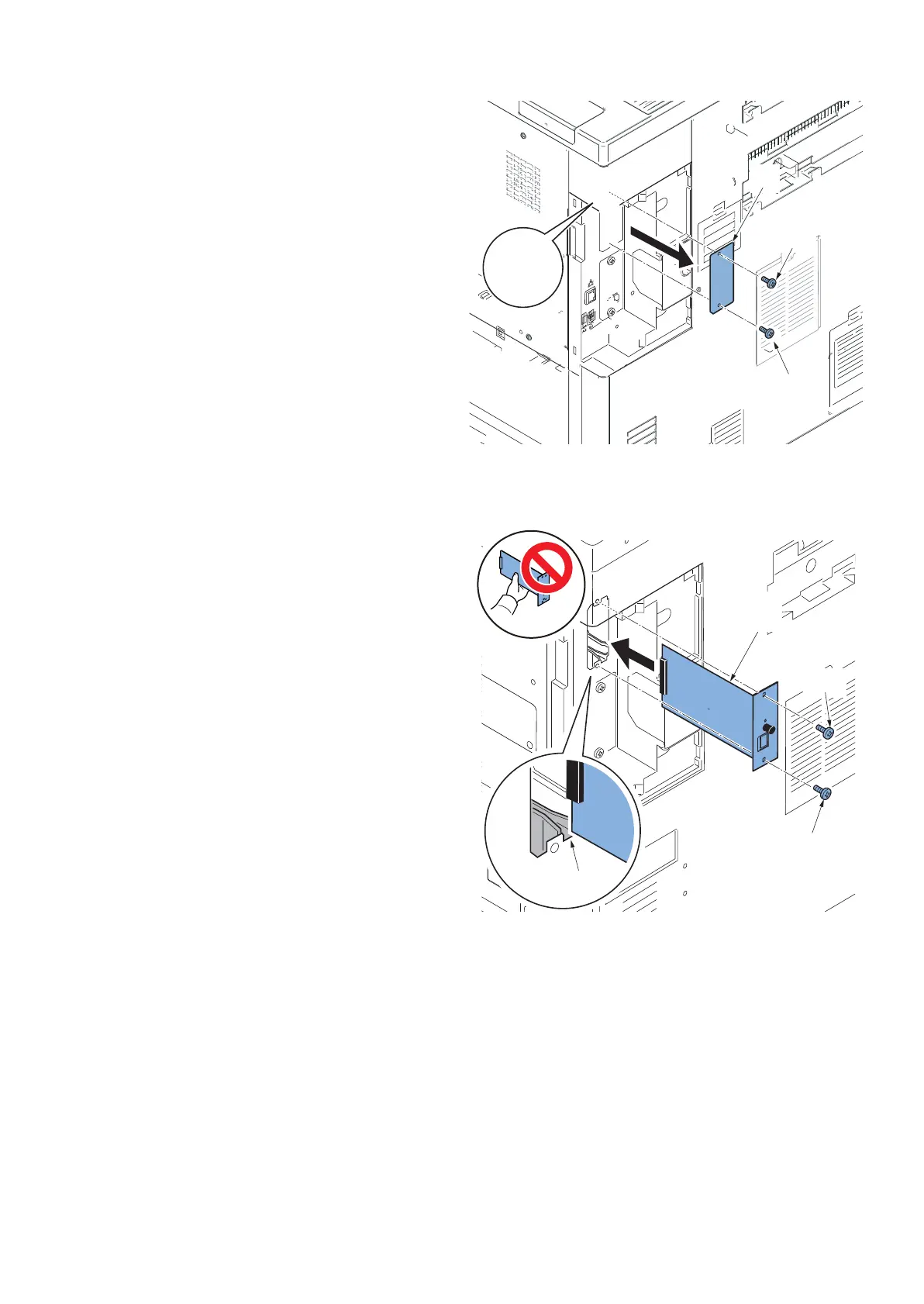
4. Remove two screws(a)(M3×8) and then remove
the OPT2 slot cover (b).
Figure 2-86
5. Insert the Gigabit Ethernet extension kit (b) along
the OPT2 groove(a), fix with two screws(c)(M3×8)
which is removed in the procedure 4.
*: Don't touch directly the terminal of Gigabit Ethernet
extension kit.
When inserting Gigabit Ethernet extension kit, you
have to hold PWB upper and lower parts or protu-
berance.
Figure 2-87
OPT1
OPT2
b
a
c
c