KARA
KARAKARA
KARA
®
®®
®
M
MM
MO
OO
ODULAR
DULARDULAR
DULAR WST
WST WST
WST
®
®®
®
SYSTEM
SYSTEM SYSTEM
SYSTEM
rigging procedures using
rigging procedures using rigging procedures using
rigging procedures using
kara
karakara
kara-
--
-minibu
minibuminibu
minibu
VERSION 1.0
KARA_SRM_EN_1-0
w w w . l - a c o u s t i c s . c o m
44
4444
44
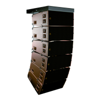
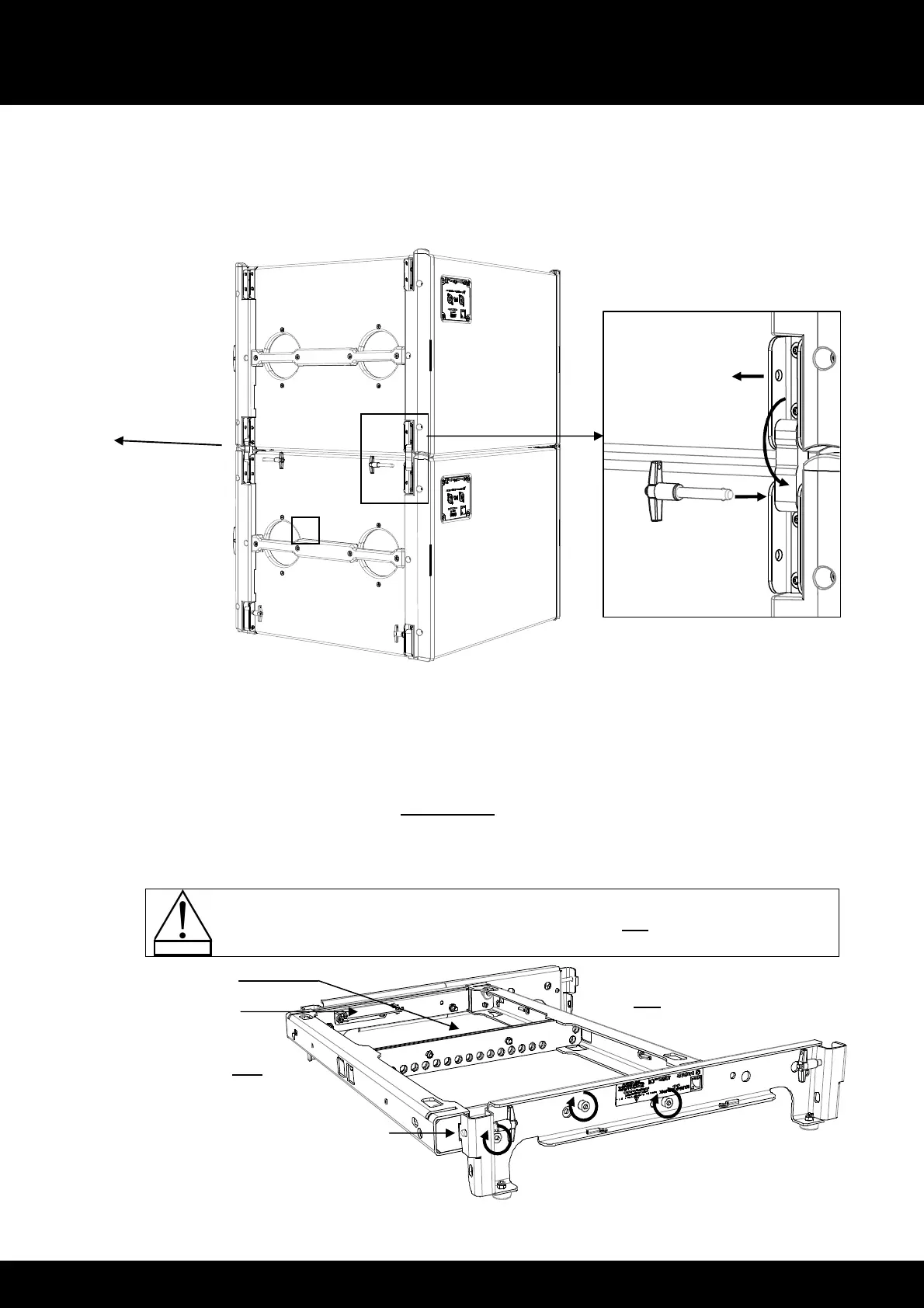
3. Attach SB18#2 to SB18#1 as follows:
a. Remove a T-BLP from SB18#2.
b. Rotate the link arm down.
c. Secure the link arm to SB18#1 by re-inserting the T-BLP into the SB18#1 top link point.
d. Repeat this procedure until all four arms are secured to SB18#1.
Figure 48: Attaching SB18#2 to SB18#1
4. Repeat steps 2 and 3 until all SB18 composing the array are assembled.
5. Assemble a KARA-MINIBU/KARA-MINIBUEX stacking platform as follows:
a. Turn the KARA-MINIBU so that the text of the identification plate is upside down.
b. Position a first KARA-MINIBUEX on the laser plate side of the KARA-MINIBU by turning it feet pointing down
and inserting the stud into the slit of the KARA-MINIBU located near the laser plate.
c. Drive 3 bolts to the 3 holes shown in Figure 49 (6 mm hex bit, 13 mm hex key, 7 N.m/63 in.lb
f
).
d. Repeat the procedure with a second KARA-MINIBUEX on the other side of the KARA-MINIBU.
Place the stacking platform in rear extension configuration only [9.3.1].
Figure 49: Assembling a KARA-MINIBU/KARAMINIBUEX stacking platform
b. Stud inserted into slit
 Loading...