KARA
KARAKARA
KARA
®
®®
®
M
MM
MO
OO
ODULAR
DULARDULAR
DULAR WST
WST WST
WST
®
®®
®
SYSTEM
SYSTEM SYSTEM
SYSTEM
rigging procedures using
rigging procedures using rigging procedures using
rigging procedures using
kara
karakara
kara-
--
-minibu
minibuminibu
minibu
VERSION 1.0
KARA_SRM_EN_1-0
w w w . l - a c o u s t i c s . c o m
32
3232
32
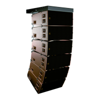
6.3 Stacking a KARA standalone array
6.3.1 Modeling and safety
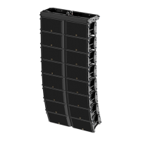
A KARA array must be stacked onto a KARA-MINIBU/KARA-MINIBUEX platform (platform stacked array).
Any platform stacked array must be modeled before installation so as to ensure acoustical conformity. This can be
done using L-ACOUSTICS
®
SOUNDVISION Software [3.4] which will assist the user to:
• Determine the number of required KARA enclosures.
• Calculate the inter-enclosure angles.
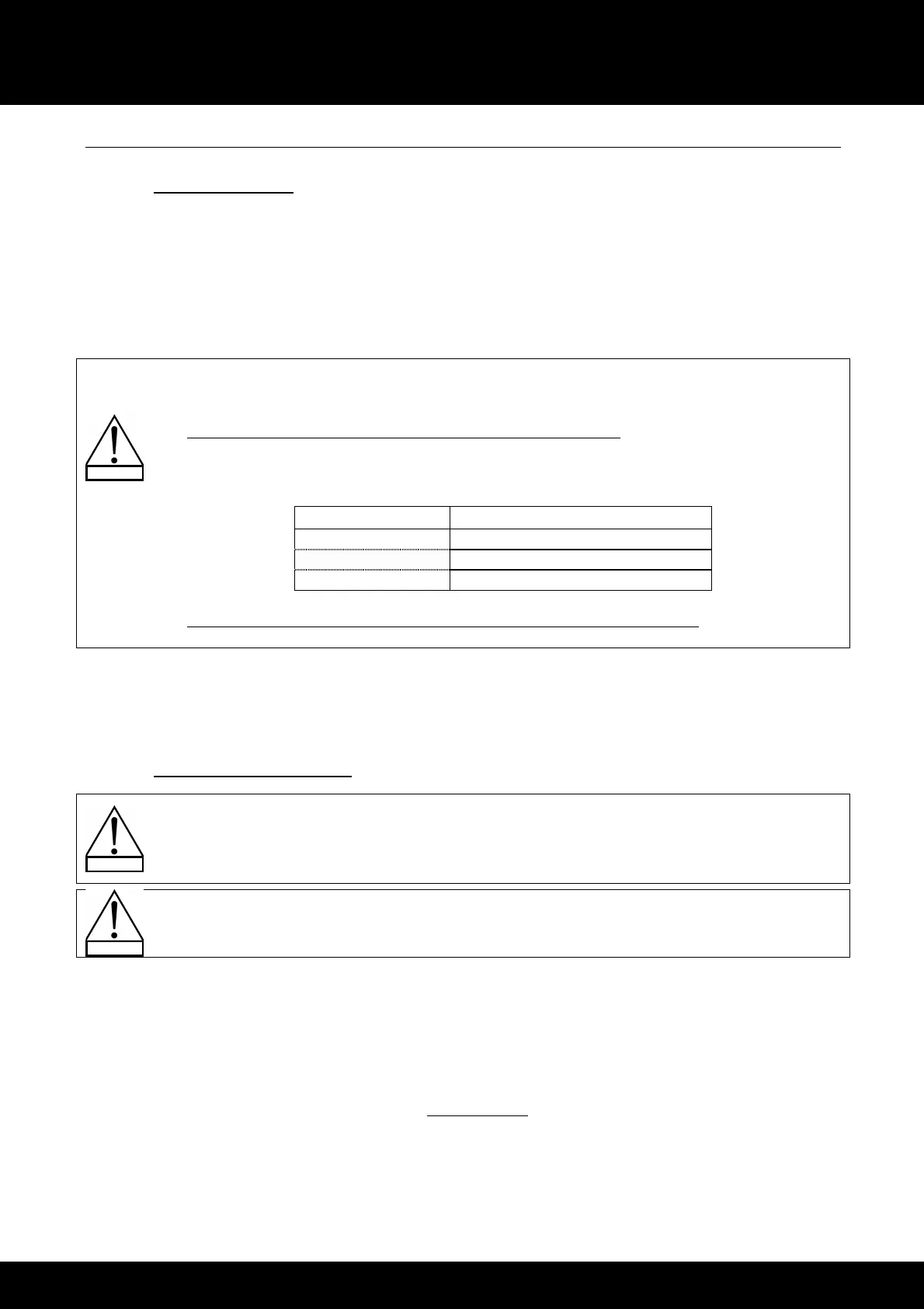
A platform stacked array requires to be installed on a perfectly horizontal and regular surface. It can be
composed of a maximum of 6 KARA enclosures along with all loudspeaker cables (refer to the KARA
User manual [3.4]) within the following setup safety limits:
• If the KARA array is flat (all inter-enclosure angles are close to 0°), the platform must be installed in
front extension configuration (refer to [9.3.1]) and the site angle of the bottom KARA must be set
within the range given in Table 2 (refer to [9.3.2] for angle settings):
Table 2: Platform stacked KARA array safe configurations
Number of KARA Bottom KARA authorized angle range
1 - 3 From -15° to +5°
4 From -11° to +5°
5 - 6 From -7.5° to +5°
• If the KARA array is strongly curved (all inter-enclosure angles are close to 10°), the platform must be
installed in rear extension configuration (refer to [9.3.1]).
The KARA, KARA-MINIBU, and KARA-MINIBUEX fully integrated rigging systems allow assembling the array with no
need for any external accessory. The following first procedure describes how to assemble a vertical KARA platform
stacked array. The second procedure describes how to disassemble the array.
6.3.2 Array assembling procedure
All along the procedure:
STRICTLY follow the sequence of the successive steps.
SYSTEMATICALLY verify that each BLP is fully inserted.
SYSTEMATICALLY verify that each bolt is fully driven on the KARA-MINIBUEX.
For clarity purposes the loudspeaker cabling procedure will not be described.
The loudspeaker cables will not be represented in the figures.
Required tools
Electric screwdriver with torque selector (N.m or in.lb
f
), 6 mm hex bit, 13 mm hex key.
Procedure
1. Assemble a KARA-MINIBU/KARA-MINIBUEX stacking platform as follows:
a. Turn the KARA-MINIBU so that the text of the identification plate is upside down.
b. Position a first KARA-MINIBUEX on the laser plate side of the KARA-MINIBU by turning the KARA-
MINIBUEX feet pointing down and inserting the stud into the slit of the KARA-MINIBU located near the laser
plate.
c. Drive 3 bolts to the 3 holes shown in Figure 35 (6 mm hex bit, 13 mm hex key, 7 N.m/63 in.lb
f
).
d. Repeat the procedure with a second KARA-MINIBUEX on the other side of the KARA-MINIBU.
 Loading...