KARA_SRM_EN_1-0
w w w . l - a c o u s t i c s . c o m
43
4343
43
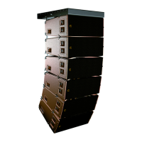
6.4 Stacking a SB18/KARA mixed array or a SB18 standalone array
6.4.1 Modeling and safety
A SB18/KARA mixed array or a SB18 standalone array must be stacked directly on the ground (ground stacked
array).
Any SB18/KARA ground stacked array must be modeled before installation so as to ensure acoustical conformity.
This can be done using L-ACOUSTICS
®
SOUNDVISION Software [3.4] which will assist the user to:
• Determine the number of required KARA enclosures (acoustic data not available for subwoofers).
• Calculate the inter-enclosure angles.
A ground stacked array must be installed on a perfectly horizontal and regular surface. It can be
composed of a maximum of 4 SB18/6 KARA or 8 SB18 enclosures within the setup safety limits given in
Table 3 regarding the angle between the top SB18 and the bottom KARA (refer to [9.3.2] for angle
settings):
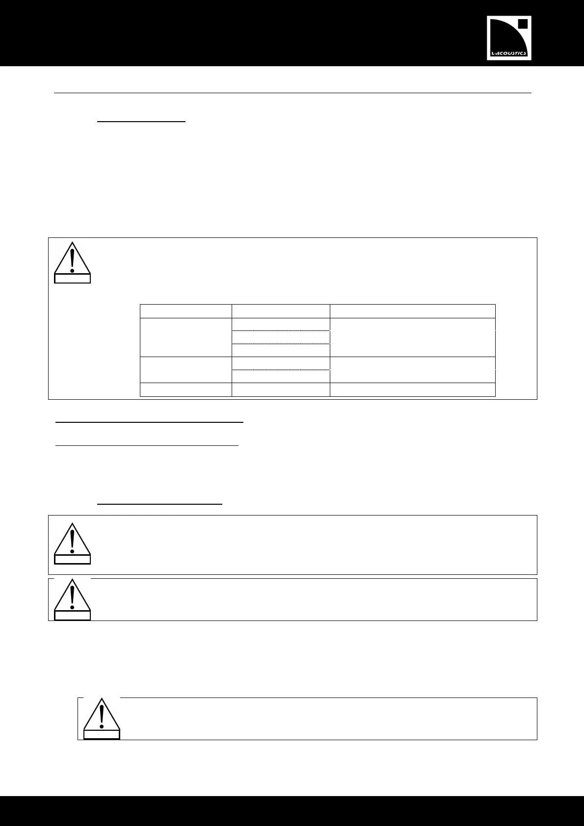
Table 3: Ground stacked SB18/KARA array safe configurations
Number of SB18 Number of KARA Bottom KARA authorized angle range
1 - 2 From -15° to +5°
3 From -5° to +5° 1
4 - 6 From -4° to +5°
1 - 5 From -15° to +5°
2
6 From -12° to +5°
3 - 4 1 - 6 From -15° to +5°
SB18/KARA mixed array assembling procedure: Apply [6.4.2].
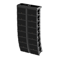
SB18 standalone array assembling procedure: Stack a first SB18 on the ground, front face logo down. Stack a second
SB18 onto the first one and attach it by applying [6.2.2, step 2c]. Repeat the procedure until all SB18 composing the
array are assembled. While installing, follow the IMPORTANT indication given below.
6.4.2 Array assembling procedure
All along the procedure:
STRICTLY follow the sequence of the successive steps.
SYSTEMATICALLY verify that each BLP is fully inserted.
SYSTEMATICALLY verify that each bolt is fully driven on the KARA-MINIBUEX.
For clarity purposes the loudspeaker cabling procedure will not be described.
The loudspeaker cables will not be represented in the figures.
Required tools
Electric screwdriver with torque selector (N.m or in.lb
f
), 6 mm hex bit, 13 mm hex key.
Procedure
1. Bring a first SB18 (SB18#1) to the rigging location, remove the dolly board, and stack it on the ground logo up.
Turn the front faces of all SB18 composing the array towards the audience to obtain an
omnidirectional acoustic pattern or turn one SB18 every fourth from front to rear to obtain a
cardioid acoustic pattern (refer to the SB18 User manual [3.4]).
2. In the same way, stack a second SB18 (SB18#2) onto SB18#1.
 Loading...