KARA_SRM_EN_1-0
w w w . l - a c o u s t i c s . c o m
11
1111
11
6
66
6 INSTALLATION
INSTALLATIONINSTALLATION
INSTALLATION
6.1 Flying a KARA standalone array
6.1.1 Modeling and safety
Any loudspeaker assembly must be modeled before installation so as to ensure acoustical and mechanical conformity.
This can be done using L-ACOUSTICS
®
SOUNDVISION Software [3.4] which will assist the user to:
• Determine the number of required KARA enclosures.
• Calculate the KARA-MINIBU site angle and the inter-enclosure angles.
• Check the mechanical conformity of the loudspeaker assembly.
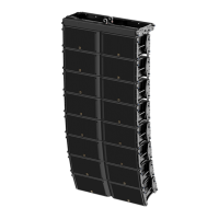
The KARA-MINIBU can nominally fly an array of up to 6 KARA along with all loudspeaker cables (refer to
the KARA User manual [3.4]). However, this maximum number can decrease in line with the array
curvature.
ALWAYS refer to the mechanical data and warning indications provided in SOUNDVISION software
(Mechanical Data section) to verify the mechanical conformity of the loudspeaker assembly before
installation.
The KARA and KARA-MINIBU fully integrated rigging systems allow assembling the array with no need for any external
accessory.
The following first procedure describes how to fly a vertical KARA array under a KARA-MINIBU. It is recommended to
assemble the KARA by successively adding arrays of 3 enclosures (called ARRAY#1 and ARRAY#2 in the order of
appearance in the procedure).
The second procedure describes how to disassemble the array.
6.1.2 Array assembling procedure
All along the procedure:
STRICTLY follow the sequence of the successive steps.
SYSTEMATICALLY verify that each BLP is fully inserted.
SYSTEMATICALLY verify that the bolt is fully driven and secured by a safety pin on each shackle.
For clarity purposes the loudspeaker cabling procedure will not be described.
The loudspeaker cables will not be represented in the figures.
Use a strain relief to avoid mechanical stress at the connector locations due to cable weight.
The motor hooks or stingers will not be represented in the figures.
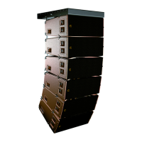
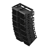
1. Bring a full KARA flight-case to the rigging location and remove the lid. Direct the front face of the KARA array
towards the audience. In the following, the array will be designated as ARRAY#1 and the enclosures as KARA#1
to KARA#3 from top to bottom.
2. Check the inter-enclosure attachments in ARRAY#1 as follows (repeat on both sides of the array):
a. Verify that each front arm (x2) is open and secured to the link holes of two KARA by two R-BLP. Note: A link
hole is indicated by a yellow circle.
b. Verify that each angle arm (x2) has the cursor aligned with the 0° angle label and is secured to two KARA by
two R-BLP, the top one being inserted into the link hole and the bottom one into angle hole 0°/2°/4°.
 Loading...