KARA
KARAKARA
KARA
®
®®
®
M
MM
MO
OO
ODULAR
DULARDULAR
DULAR WST
WST WST
WST
®
®®
®
SYSTEM
SYSTEM SYSTEM
SYSTEM
rigging procedures using
rigging procedures using rigging procedures using
rigging procedures using
kara
karakara
kara-
--
-minibu
minibuminibu
minibu
VERSION 1.0
KARA_SRM_EN_1-0
w w w . l - a c o u s t i c s . c o m
66
6666
66
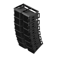
Rigging options 2 and 4 allow continuous bumper site angle setting depending on the relative heights between the
front and rear hang points (holes 1 and 17) as shown in Figure 69.
The configurations shown in Figure 69 are purely indicative.
ALWAYS refer to the mechanical data and warning indications provided in SOUNDVISION Software
(Mechanical Data section) [3.4] to verify the mechanical conformity of the loudspeaker assembly before
installation.
Figure 69: Continuous angle selection (option 4 examples)
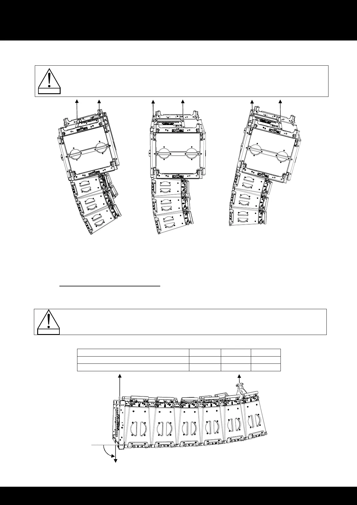
9.2.3 KARA-PULLBACK setup safety limits
The KARA-PULLBACK accessory attaches to the bottom enclosure of a KARA array to allow setting the site angle
down to -90°. However, this limit depends on the composition of the array as shown in Table 6.
ALWAYS refer to Table 6 before using the KARA-PULLBACK accessory.
Table 6: Possible downwards site angles with KARA-PULLBACK
Number of KARA enclosures in the array
6 6 3
Number of SB18 enclosures in the array
0 2 1
Maximum array site angle
-90° -90° -90°
Figure 70: 90° downwards site angle with KARA-PULLBACK
Rear extension configuration
and 0° site angle
Front extension configuration
and negative site angle
and positive site angle
 Loading...