EasyManua.ls Logo

Labconco Purifier Logic+ 30132 User Manual

Labconco Purifier Logic+ 30132
174 pages
To Next Page IconTo Next Page
To Previous Page IconTo Previous Page
Page #147 background image
Product Service 1-800-522-7658
147
Confirming Calibration Procedure-
With the cabinet operating:
1. Press the
Menu
button.
2. Press the button until the
Services
option is highlighted
(it will turn yellow).
3. Press
OK/Mute
to enter the Services menu screen.
4. Press the button until the
Diagnostics
option is
highlighted (it will turn white).
5. Press
OK/Mute
to enter the Diagnostics submenu screen.
6. Press the button until the
Airflow Sensor
option is
highlighted (it will turn white).
7. Press
OK/Mute
to enter the Airflow Sensor submenu
screen.
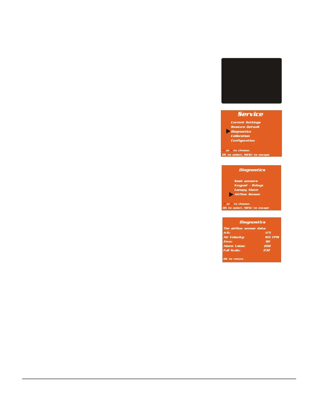
8. The display shows the following values in millivolts -
a. “Zero” – should be approximately 90-110.
b. Alarm (approximately 85% of Full scale calculated
by the cabinet)
c. Full scale - the value for inflow set during
calibration.
NOTE: There should be approximately 100 millivolts or higher difference
between the zero and operational (full scale) points. Differences
significantly lower than 100 mV may result in erratic air velocity values
being displayed.
MAIN MENU
1. MyLogic
TM
2. Settings
3. Service
or to choose,
OK to select, MENU to escape

Table of Contents

Questions and Answers:

Labconco Purifier Logic+ 30132 Specifications

General IconGeneral
FiltrationHEPA
Filter TypeHEPA
UV LightOptional
Nominal Width3 ft
Downflow Velocity0.38 m/s (75 fpm)
Filter Type (Exhaust)HEPA
Electrical Requirements115V, 60Hz
Electrical115V, 60Hz

Summary

Background Information

Quickstart Guides

Guides for initial operation and answering common questions about the Logic+.

Password and Configuration

Explains the password system and how to change cabinet configuration settings.

Calibration Procedures

Step-by-step guides for calibrating blower speed, filter life gauge, and airflow sensors.

Diagnostics and Settings

Procedures for viewing current settings, running diagnostics, and adjusting parameters.

Automated Operation Setup

Guide to configure automatic blower, light, and UV lamp operations.

Filter Life Gauge Management

Explains filter life calculation and recalibration for local conditions.

Logic+ Model Specifications

Presents detailed technical specifications for various Logic+ models in Imperial and Metric units.

Identifying Logic+ Models

Model Identification Features

Explains how to identify Logic+ cabinets by external features like serial numbers and displays.

Serial Number and Model Numbering

Details the location and meaning of serial number tags and the model numbering system.

Data Plate and Test Reports

Information on the Logic+ data plate and final inspection test report for certification.

Theory of Operation

Airflow Patterns

Overview of airflow patterns in Type A2 and Type B2 biosafety cabinets.

ECM Motor Technology

Explanation of Electronically Commutated Motor technology used in Logic+.

Electronics and Circuitry

Details the microprocessor, control board, and power supply board components.

Installation Requirements

Site Preparation and Prerequisites

Outlines site preparation and requirements before cabinet installation.

Space, Clearance, and Location

Guidelines for required space, clearances, and optimal location for the cabinet.

Exhaust and Electrical Requirements

Specifies requirements for exhaust duct connections and electrical power supply.

Utility Service Line Requirements

Specifies requirements for connecting utility service lines like gas or air.

Installation Procedures

Unpacking and Cabinet Handling

Instructions for safely unpacking, moving, and lifting the biosafety cabinet.

Cabinet Installation Methods

Procedures for installing on work surfaces or various Labconco base stands.

Utility and Accessory Connections

Instructions for connecting utility service lines and optional accessories like canopy and portals.

Drain Valve Installation

Step-by-step guide for installing the optional drain valve assembly.

Initial Operation

System Reset and Information Center

Location of the system reset switch and description of the Information Center display.

Alarms and Sash Operation

Details on alarm screens, operating the sliding sash, and starting the cabinet.

Touchpad and Menu Navigation

Explanation of the touchpad functions and navigating menu screens.

MyLogic and Settings Configuration

Guides for setting the clock, configuring Logic+ features, and managing settings.

Timer and UV Lamp Operations

Instructions for using timers and managing UV lamp settings and hourmeter.

Certification Procedures

Certifier Menu Access and Adjustments

Accessing the certifier's menu and adjusting blower speed and filter gauge.

HEPA Filter Leak Test Procedures

Information and specifications for HEPA filter leak tests on Type A and Type B models.

Inflow and Downflow Velocity Tests

Procedures for testing downflow velocities and calculating inflow velocity.

Optional Performance Tests

Procedures for optional tests like air cleanliness, light level, noise, vibration, and UV intensity.

GFCI and Other Tests

Procedure for testing the Ground Fault Circuit Interrupter.

Service Operations

Recommended Tools and Dress Components

Lists service tools and procedures for removing/installing external components.

Sash and Damper Adjustments

Instructions for sash operation, adjustment, and exhaust damper adjustment.

HEPA Filter and Prefilter Replacement

Procedures for replacing supply and exhaust HEPA filters and Type B2 prefilters.

Motor/Blower and Component Replacement

Procedures for replacing motor/blower, work surface, grille, and diffuser.

Sterilization Preparation

Steps to prepare the Logic+ for gaseous sterilization.

Electrical System Service

Fluorescent Lamp Service

Information on fluorescent lamps, including identification, specifications, and replacement.

UV Lamp and Socket Service

Instructions for changing UV lamps, replacing sockets, and module access.

Circuit Breaker and Power Supply

Procedures for managing circuit breakers and servicing the power supply board.

Motor and Diagnostic Operations

Motor testing, output signal testing, and diagnostic operations.

Wiring Diagrams

Wiring diagrams for 115 VAC and 230 VAC models.

Purifier Logic+ Accessories

Ventus Canopy Connection Kit

Information on the Ventus Canopy Connection Kit, including theory and installation.

Air Flow Sensor Kit Installation

Instructions for installing the air flow sensor kit, with and without canopy connection.

Calibration Procedures

Critical instructions for calibrating the airflow sensor and confirming the procedure.

Service Fixture and IV Bar Kits

Information and installation procedures for Service Fixture and IV Bar Kits.

UV Lamp and Prefilter Kits

Installation procedures for UV Lamp Kits and Prefilter Kits.

RS-232 Connection and Data Output

Instructions for RS-232 connection kits, data output, and relay contacts.

Miscellaneous

Troubleshooting Common Issues

Table of common problems, their causes, and suggested corrective actions.

Replacement Parts Identification

Lists of replacement parts for Type A1/A2 and Type B2 biosafety cabinets.

Cabinet Dimensions

Diagrams and data showing the physical dimensions of the biosafety cabinets.

Related product manuals