Create a Transfer Map
A transfer map must be created for each source microplate. The transfer map defines which source microplate wells contain
reagent that will be transferred to the destination plate.
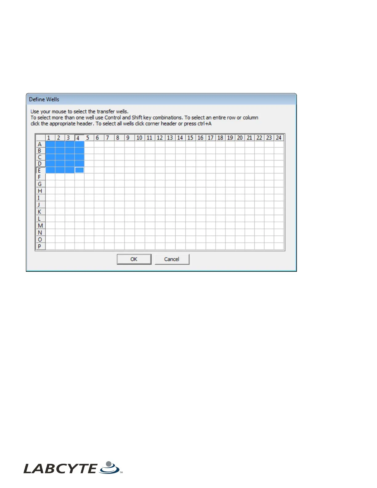
When you click the View/Define button, the Define Wells dialog box opens.
Figure 61: Define Wells dialog box
The Define Wells dialog box shows a simple grid that represents the microplate. Each source microplate well is represented by a
grid square. The user selects the microplate wells from which fluid will be transferred.
Selected wells (highlighted in blue) will be transferred when the protocol is run. The dialog box shown above defines a liquid
transfer from wells A1 through E4. There are several methods to define which wells belong in the transfer map.
l Click a single well to select it and clear all other selected grid squares.
l Hold the Control key down and click in individual wells. Each well is selected in turn.
l After making a well selection, hold down the Shift key and click in another well. All wells in a rectangle defined by the two
wells are selected.
l Click on a row label or a column label. The entire row or column will be selected.
l Click and drag the mouse point to define a rectangle of wells in one move.
l If a group of wells is selected and another well (or group of wells) must also be selected, hold the Control key down so that
the original group of wells is not cleared.
l All wells can be selected by clicking in the upper-left square (above the row labels). Another method is to press CTRL-A (if
at least one well is already selected).
Echo Liquid Handler Software CHAPTER 5 | Software
102