C: X center spacing: Dimension C specifies the horizontal distance between well centers in millimeters. That is, the distance
between wells A1, A2, A3, and so on.
Example: For a 384PP plate type, C is 4.5 mm.
The valid range for C is 0.05 mm to 9.00 mm.
Refer to ANSI/SBS 4-2004 for more information.
D: Y center spacing: Dimension D specifies the vertical distance between well centers in millimeters. That is, the distance
between wells A1, B1, C1, and so on.
Example: For a 384PP plate type, D is 4.5 mm.
The valid range for D is 0.05 mm to 9.00 mm.
Refer to ANSI/SBS 4-2004 for more information.
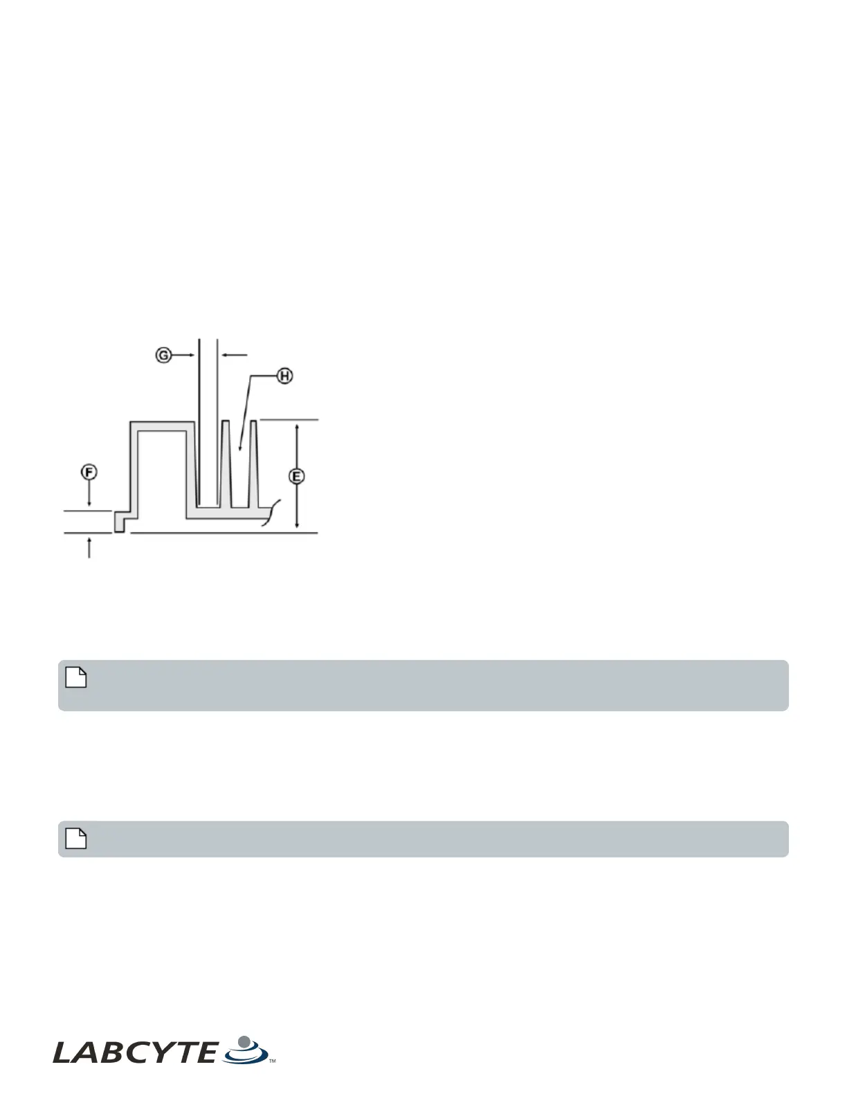
Figure 72: Plate dimensions E, F, G, and H
E: Plate height: Dimension E specifies the overall height of the plate in millimeters.
Example: For a 384PP plate type, E is 14.4 mm.
Refer to ANSI/SBS 2-2004 for more information.
The valid range for E is 6.50 mm to 16 mm (higher plate height is not included in ANSI/SBS standards).
Note: When using barcode labels on higher plate heights (for example, 16 mm), align the barcode label with the top of the
plate to ensure proper scanning.
F: Flange height: Dimension F specifies the height of the plate’s flange in millimeters. The Echo Liquid Handler supports the SBS
standard short, medium, and tall flange heights. Select the correct one from the drop down list.
Example: For a 384PP_AQ_BP plate type, F is 2.41 mm.
The valid choices for F are 2.41, 6.10, or 7.62 mm.
Refer to ANSI/SBS 3-2004 for more information.
Note: The flange height property is currently used for customer plate dimension management.
G: Well bottom width: Dimension G specifies the width of the well at its bottom in millimeters. This is not an SBS-specified
dimension. It is used for source plates and is not necessary for destination plates.
Example: For a 384PP_AQ_BP plate type, G is 3.3 mm.
The valid range for G is 0.00 to 86.00 mm.
H: Well volume: Dimension H specifies the volume of the well in microliters.
Echo Liquid Handler Software CHAPTER 5 | Software
114