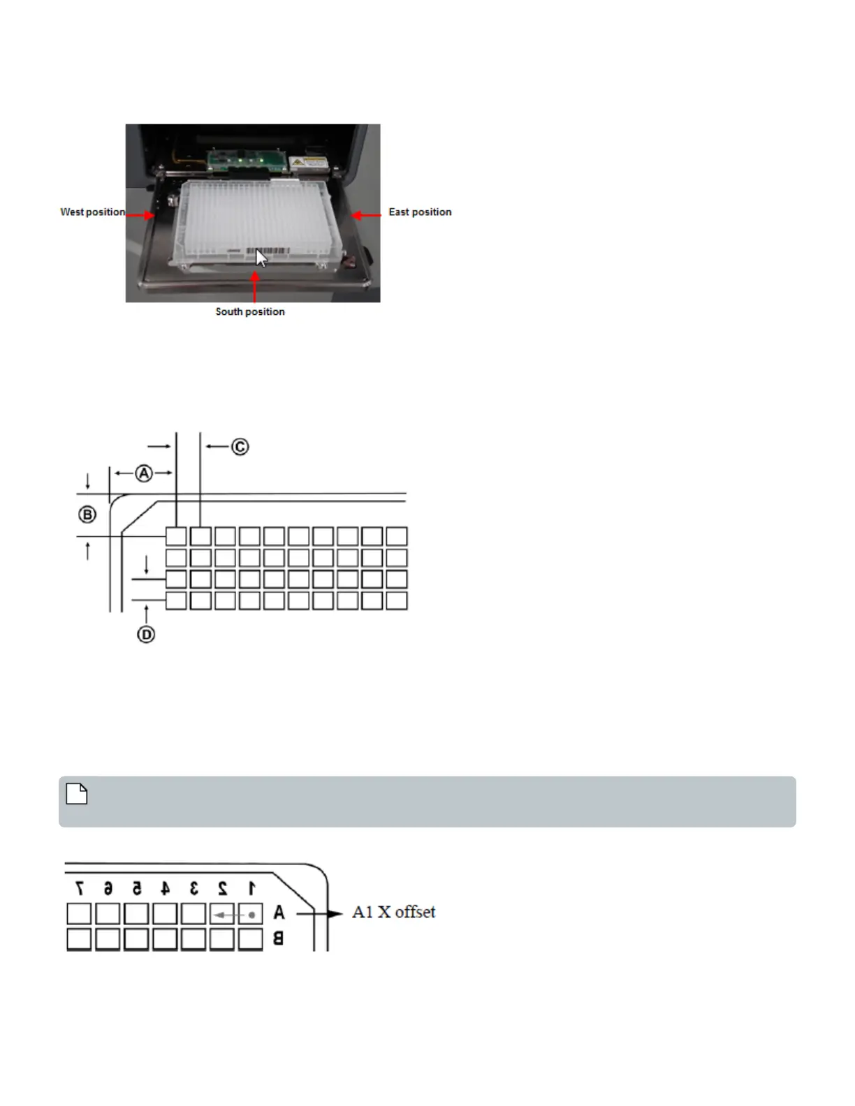
Figure 69: Selecting barcode locations
Plate Dimensions
Two illustrations identify the destination plate dimensions that must be entered. These dimensions may already be specified in
the SBS standards.
Figure 70: Plate dimensions A, B, C, and D
A and B:Well A1 X/Y offsets. Dimensions A and B locate the center of well A1 in relation to the plate’s left and top outside edges. A
specifies the A1 well center to the left outside edge in millimeters. B specifies the A1 well center to the top outside edge in
millimeters.
Examples: For a 384PP source plate type, A is 12.15 mm and B is 9.05 mm.
The valid range for A is 0.00 mm to 128.00 mm.
The valid range for B is 0.00 mm to 86.00 mm. Refer to ANSI/SBS 4-2004 for more information.
Note: The Echo Liquid Handler's frame of reference for the destination is an inverted microplate. Increasing the A1-X
offset will shift the inverted microplate to the right, and therefore drop placement would be further left.
Figure 71: Inverted destination microplate
113 PN | 001-11665
USER GUIDE | Echo® 525 Liquid Handler User Guide Echo Liquid Handler Software