PLMNL0243 REV. A, Effective Date: 03/24/16 20 FiberMINI ™ 2.0 Operation Manual
On the left side is the Ground
Voltage check. This meter is used to
verify that the voltage reading at
ground is close to zero. The upper
limit can also be specified by
selecting Ground Limit from the
Settings menu.
The center section allows the gain
used with V
DIF
to be viewed and
adjusted.
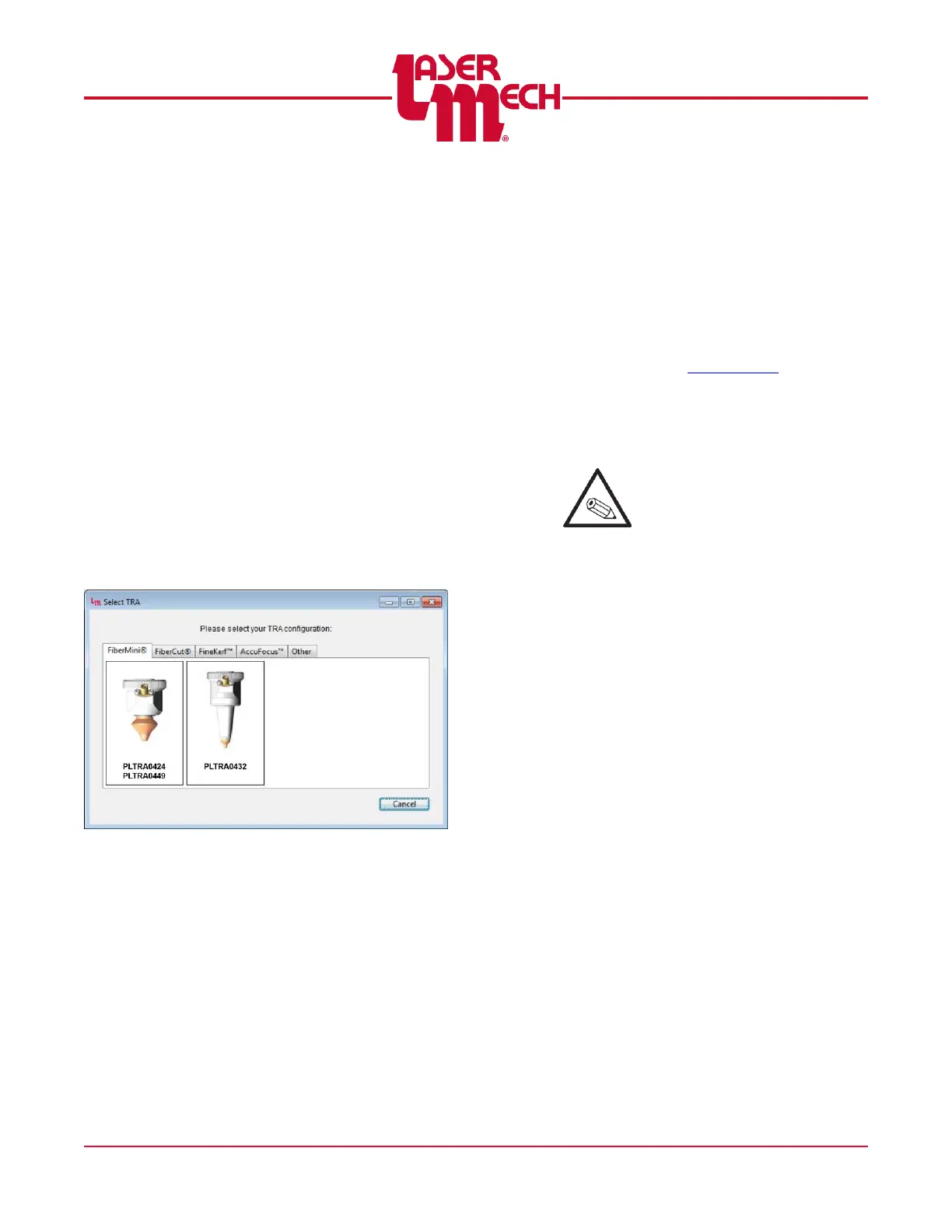
TRA Selection
The TRA can be changed by
selecting Select TRA from the
Settings menu. The TRA Selection
Window includes a library of tip
assemblies that the Universal HSU
has been designed to work with.
See Figure 29. The libraries
correspond to the four most
common product lines.
TRA Selection Window
Figure 29
Navigate through the tabs to locate
the picture and part number that
matches your TRA. If you are
unable to find your exact model,
please contact Laser Mechanisms
for assistance in selecting a suitable
substitute. After selecting a new
TRA, it is important to select an
active curve that is designed for that
TRA. See Section 4.4.4 for
information on selecting the active
curve.
Note: Basic+ Interfaces are
shipped with no specific TRA
setting.You MUST choose a
TRA setting the first time you
power up the HSU. Once the
TRA is set, you will only need
to change the setting if a
different TRA is used.