PLMNL0243 REV. A, Effective Date: 03/24/16 54 FiberMINI ™ 2.0 Operation Manual
Calculating the Standoff Error
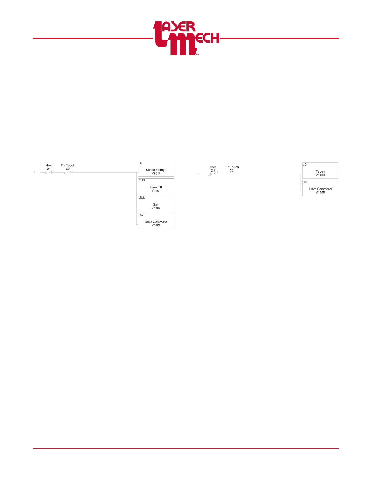
A simple calculation can be used to generate a
standoff error signal that is assigned to the Drive
Command. See Figure 67. This allows the Z-
axis to track the surface of the part and maintain
a constant standoff value. Rung 4 takes the
Sense voltage, subtracts the desired standoff
value (V1401) and multiplies the result by a Gain
value (V1402). The final result is assigned to the
Drive Command.
Figure 67
Setting the Drive Command on
Tip-Touch
In some instances it may be desirable to have
the Drive Command revert to constant value
when Tip-Touch is active to move the Z-axis
away from the part. See Figure 68. In the
example shown in Rung 5, the value V1403 will
be sent to the Drive Command V1400. Typically
setting the Drive Command to 10V will move the
Z-axis up.
Figure 68