T
HE
A
NATOMY OF THE
I
MPULSE
Page 6
Electronic Copy of LTI’s Impulse User’s Manual 8
th
Edition © October 1998
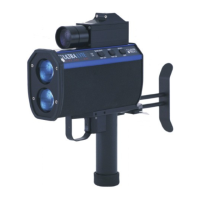
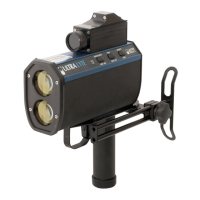
Receive lens
Transmit lens
g
t
ng scope
Front View
LCD screen
Battery
Button panel
Button panel
Rear View
Serial port
connector
Speaker
compartment
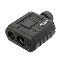
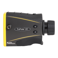
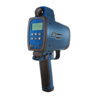
The Impulse consists of a laser range sensor, a
fluid tilt sensor (Impulse 200 only), a sighting
scope, and a data output port. The sensors are
integrated with software controls and accessed
through the two 3-button panels on either side of
the unit and a liquid crystal display (LCD) screen on
the rear panel.
Sensors
The Impulse laser range sensor provides
immediate access to slope distance values. The
Impulse determines distance by measuring the time
of flight of short pulses of infrared light. The
Impulse has a broad spectrum of sensitivity and
can work with both reflective and nonreflective
targets.
The maximum measurement distance, about 575
meters (1880 feet), varies with target and
environmental conditions.