T
HE
A
NATOMY OF THE
I
MPULSE
Page 7
Electronic Copy of LTI’s Impulse User’s Manual 8
th
Edition © October 1998
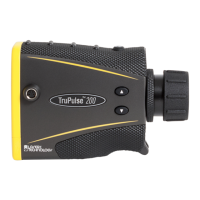
In the Impulse 200, the tilt sensor measures vertical
angles, which the Impulse uses to calculate height
and elevation and to determine slope-reduced
horizontal distances. The tilt sensor is capable of
taking full 360 degree angular measurements,
which is displayed by the tilt sensor as ±180
degrees. The instrument held level is at 0 degrees,
and is rotated up through +180 degrees, and down
through -180 degrees.
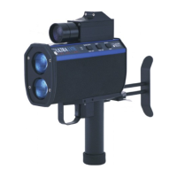
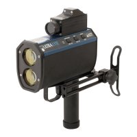
Sighting Scope
The sighting scope mounted atop the Impulse will
vary depending upon which option you chose.
The single-power sighting scope features an in-
scope, red aiming dot to help you aim accurately to
the target. You can vary the intensity of the dot to
account for different
lighting conditions. See “Setting the Scope Dot
Intensity” under Taking a Basic Measurement.
The variable-power sighting scope features an in-
scope crosshair, and allows you to adjust the
magnification of the scope.
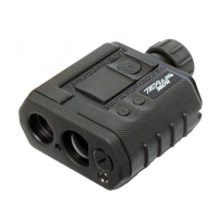
Front and Back Panels
The Impulse has two lenses on the front panel. The
top lens transmits infrared laser signals. The
bottom lens receives signals back from the target
and feeds signal information to the instrument’s
internal circuitry.
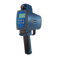
The back panel contains an LCD display screen,
battery compartment access, and a serial port
connector that allows you to connect the instrument
to a data collector or notebook computer.