R
EALIGNING THE
S
COPE
Electronic Copy of LTI’s UltraLyte User’s Manual – 7
th
Edition June 1998
55
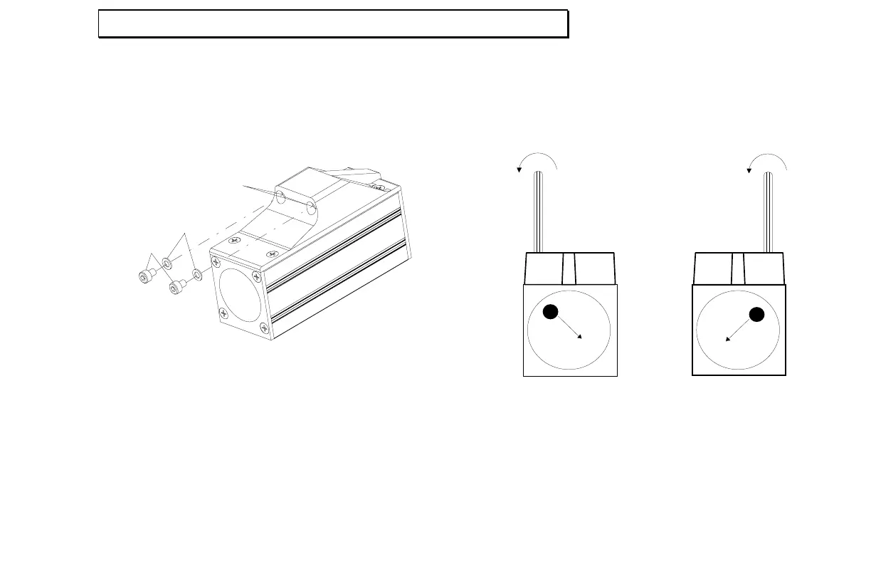
Adjustment Screws
The scope adjustment screws are in the top front
panel of the scope, protected by cover screws. To
gain access, remove the cover screws with a 2.5mm
Allen wrench.
Cover screw
Plastic washer
Adjusting screw
1.5 mm
2.5 mm
Warning: Each cover screw assembly includes a
small plastic washer. It is imperative that you not
lose the washers. Failing to replace them
renders the scope susceptible to water damage.
Once the adjustment screws are exposed, turn them
with a 1.5mm Allen wrench to adjust the position of
the scope aiming dot, as shown in the following
illustration:
Scope rear view Scope rear view
For Internal Use Only. Not for Distribution.