49
ECP5 and ECP5-5G High-Speed I/O Interface
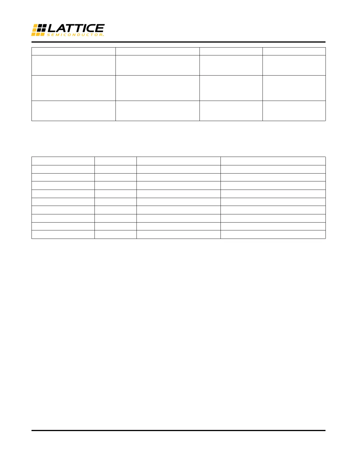
Table 9 shows how the interfaces are selected by Clarity Designer based on the selections made in the Pre-Config-
uration Tab.
Table 9. Clarity Designer DDR_Generic Interface Selection
Refer to the High-Speed DDR Interface Details section to see implementation details for each of these interfaces.
Configuring 7:1 LVDS Interface Modules
To build a 7:1 LVDS DDR interface, select GDDR_7:1 option under Architecture Modules – IO in the Catalog Tab of
Clarity Designer. Enter the name of the module.
Figure 44 shows the type of interface selected as “GDDR_7:1” and module name entered. This module can then
be configured by clicking the Customize button.
Actual Clock Frequency Displays the achieved PLL output
clock frequency
Actual PLL output Fre-
quency achieved based
on interface requirement
CLKI Input Buffer Type The I/O Standard for the PLL Ref-
erence Clock
List of Legal Input Stan-
dards,
None (if coming from fab-
ric)
LVC MO S 25
Enable MIPI Filter Soft IP for Low
Speed Data
Generates the MIPI Filter soft IP in
module for Interface = Receiver
MIPI
Enable, Disable Disable
Interface Type Gearing Ratio Alignment Default Interface
Receive 2:1 Edge-to-Edge GDDRX1_RX.SCLK.Aligned
Receive 2:1 Centered GDDRX1_RX.SCLK.Centered
Receive 4:1 Edge-to-Edge GDDRX2_RX.ECLK.Aligned
Receive 4:1 Centered GDDRX2_RX.ECLK.Centered
Receive MIPI 4:1 Centered GDDRX2_RX.ECLK.MIPI
Transmit 2:1 Edge-to-Edge GDDRX1_TX.SCLK.Aligned
Transmit 2:1 Centered GDDRX1_TX.SCLK.Centered
Transmit 4:1 Edge-to-Edge GDDRX2_TX.ECLK.Aligned
Transmit 4:1 Centered GDDRX2_TX.ECLK.Centered
GUI Option Description Values Default Value
 Loading...


