Note: Make sure to match the drive backplane and NVMe switch card connectors as following:
Table 21. Drive backplane and NVMe switch card connectors
AnyBay/NVMe drive backplane
connector
Switch card connector
0-1
C0
2-3
C1
4-5
C0
6-7
C1
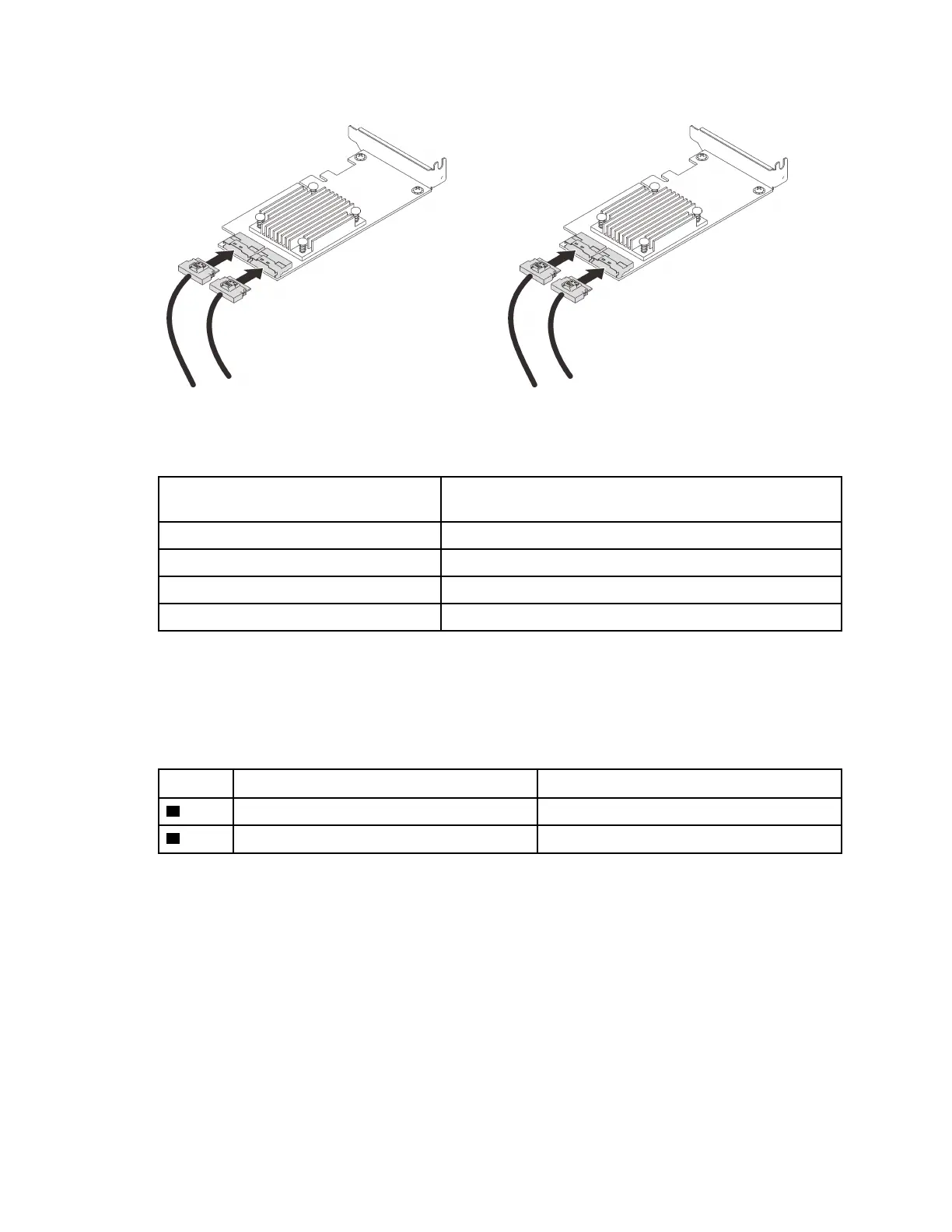
Figure 31. Connecting cables to the NVMe switch cards
Step 5. Open the retainers of x16/x16 4U PCIe riser cage, and install the two NVMe switch cards to
corresponding slots:
Table 22. NVMe switch cards and corresponding PCIe slot numbers
AnyBay/NVMe drive backplane connectors PCIe slot number
1
0-1, 2-3
Slot 10
2
4-5, 6-7
Slot 12
54 ThinkSystem SR860 V2 Maintenance Manual

 Loading...


