x8/x8/x8/x8 PCIe FH riser cage
See this section to locate the connectors in the x8/x8/x8/x8 4U PCIe riser cage.
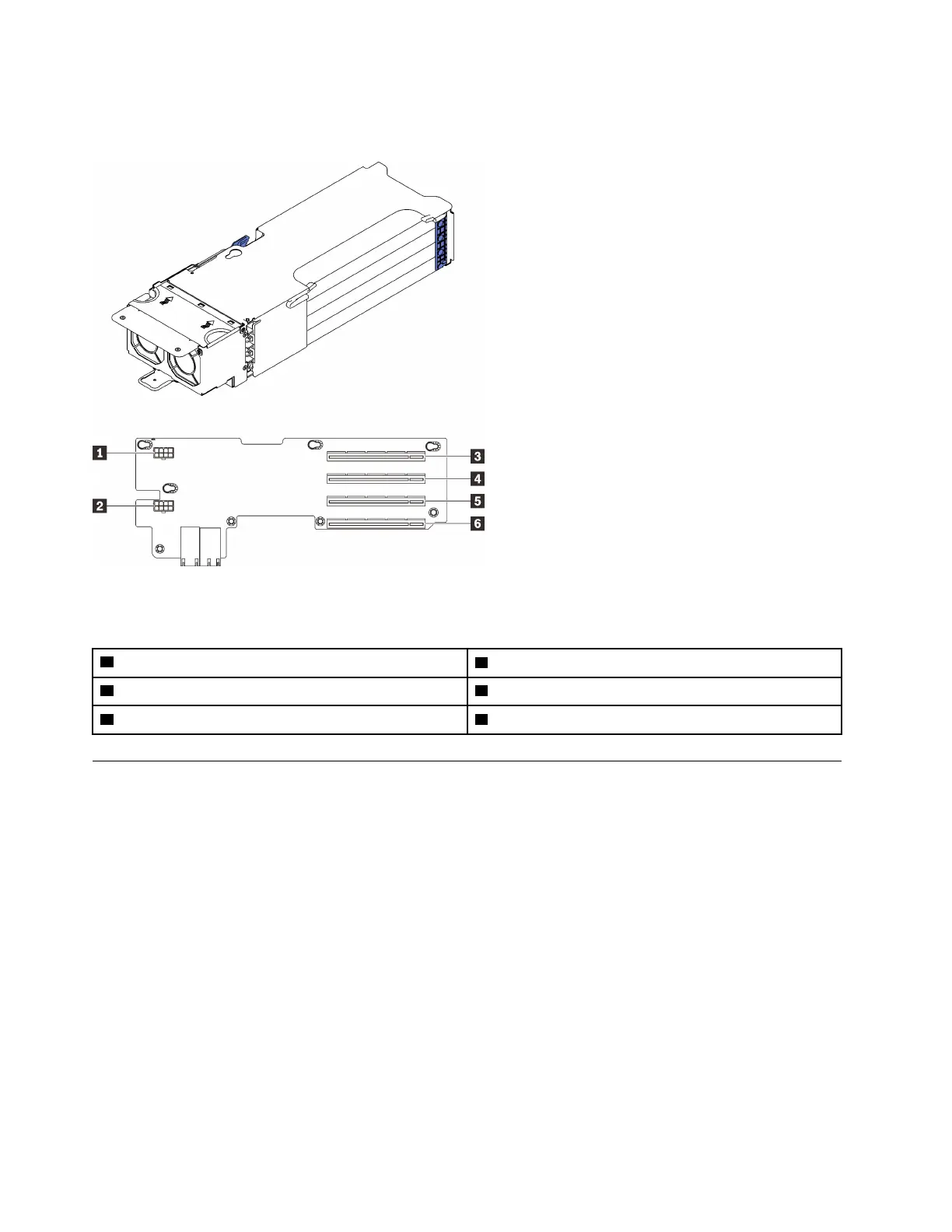
Figure 18. x8/x8/x8/x8 PCIe FH Riser Cage
Table 13. Connectors on x8/x8/x8/x8 PCIe FH Riser Cage
1 Auxiliary power connector
4 PCI Express 3.0 x8 (slot 2/10)
2 Auxiliary power connector
5 PCI Express 3.0 x8 (slot 3/11)
3 PCI Express 3.0 x8 (slot 1/9) 6 PCI Express 3.0 x8 (slot 4/12)
Switches, jumpers, and buttons
The following illustration shows the location of the switches, jumpers, and buttons on the server.
Note: If there is a clear protective sticker on the top of the switch block, you must remove and discard it to
access the switch.
38
ThinkSystem SR860 V2 Maintenance Manual

 Loading...


