Front view
This section contains information about the controls, LEDs, and connectors on the front of the server.
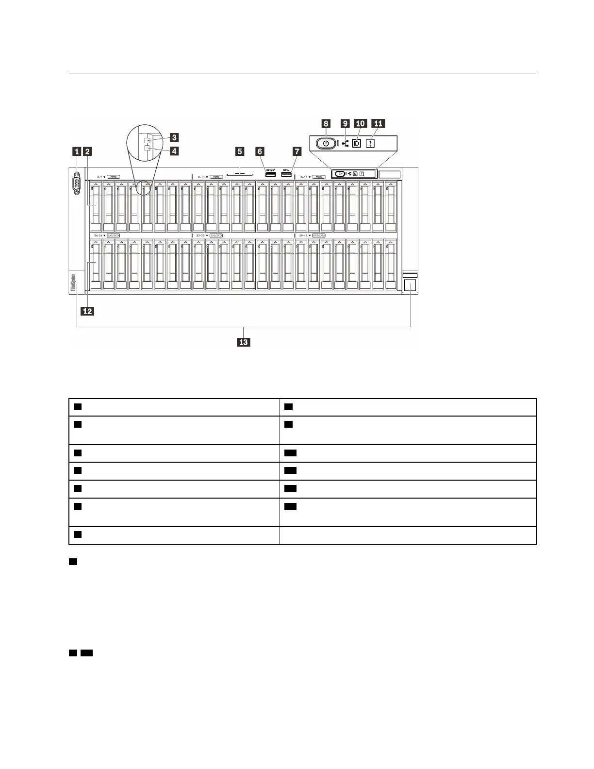
Figure 5. Front view
Table 3. Components on the front view
1
“VGA connector (optional)” on page 15
8
“Power button/LED (green)” on page 16
2
“2.5-inch drive bays” on page 15 (bay 0 to
23)
9
“Network activity LED (green)” on page 17
3
“Drive activity LED (green)” on page 16
10
“Identification button/LED (blue)” on page 17
4
“Drive status LED (yellow)” on page 16
11
“System error LED (yellow)” on page 17
5
“Pull-out information tab” on page 16
12
“2.5-inch drive bays” on page 15 (bay 24 to 47)
6
“USB” on page 16 1 (USB 2.0 with Lenovo
XClarity Controller management)
13
“Rack release latches” on page 17
7
“USB” on page 16 2 (USB 3.1)
1 VGA connector (optional)
Connect a monitor to this connector.
Notes:
• When the optional front VGA connector is in use, the rear one will be disabled.
• The maximum video resolution is 1920 x 1200 at 60 Hz.
2 / 12 2.5-inch drive bays
Install 2.5-inch drives to these bays. See
“Install a 2.5-inch hot-swap drive” on page 146 for more details.
Chapter 2. Server components 15

 Loading...


