9300 Servo PLC
System blocks
2.8 DFIN_IO_DigitalFrequency
2-29
L
ServoPLC EN 2.0
2.8.1.1 Technical data for the connection of X9
1
2
3
4
5
6
7
8
9
l = max. 50 m
0.14
0.14
0.5
26
26
20
mm
2
AWG
B
B
A
A
GND
Lamp control
Z
Z
X9
1
2
3
4
5
6
7
8
9
1
2
3
4
5
6
7
8
9
1
2
3
4
5
6
7
8
9
X10
enable
B
B
A
A
GND
Z
Z
0.5
20
0.14
26
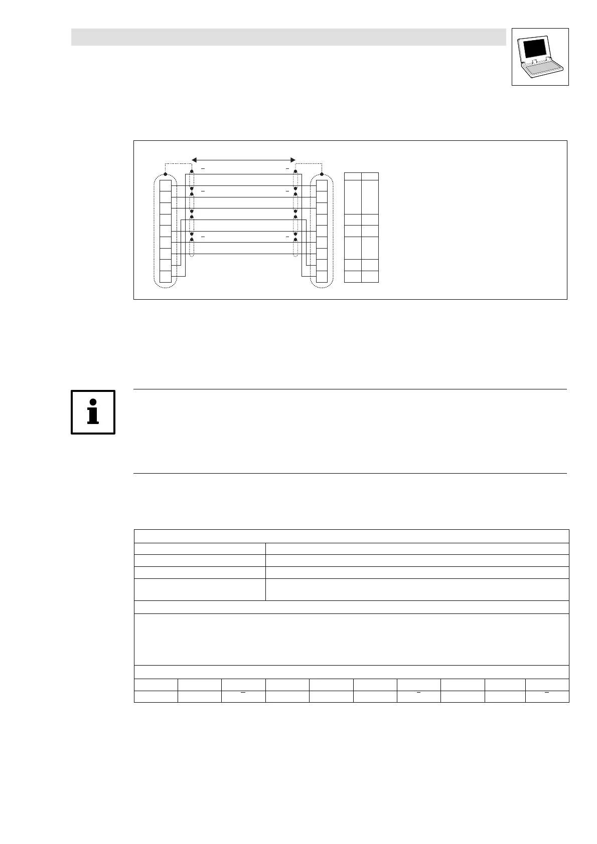
The connection i s designed as
shown in the figure:
• Use pairs of twisted
and shielded cables.
• Connect the screen at both ends.
• Do no change the cable cross-sections indicated.
Fig. 2-16 Connection of digital frequency output X10 with digital frequency input X9
Master drive
Slave drive
Cross-sections to be used
Note!
Digital frequency input (X8/X9) and digital frequency output (X10) cannot be used independently of
each other, i.e. either X8 or X9 is output at X10 (C0540 = 4, 5).
• If the configuration under C0540 selects another output for X10 (C0540 = 0, 1, 2), the digital
frequency outputs X8/X9 will be deactivated.
Digital frequency input X9
Technical data
Connection: Sub-D male connector, 9-pole
Output frequency: 0 - 500 kHz
Current consumption: max. 6 mA per channel
Possible input signals: • Incremental encoders with two 5V complementary signals (TTL-level source), shifted by 90°
• Encoder simulation of the master
Properties
• Two-track with inverse 5 V signals and zero track
• PIN 8 (LC) is for monitoring the cable and the preconnec ted c ontroller:
– When PIN 8 is LOW, the monitoring “FaultEncCable” (”SD3”) is activated.
– If the monitoring is not required, this input can be tied to +5V.
• The digital frequency input is switched off at C0540 = 0, 1 or 2.
Sub-D connector assignment (X9)
PIN 1 2 3 4 5 6 7 8 9
Signal B A A +5 V GND Z Z LC B
Digital frequency output X10
• See SB DFOUT_IO_DigitalFrequency. (^ 2-32)
efesotomasyon.com - Lenze

 Loading...


