9300 Servo PLC
System blocks
2.8 DFIN_IO_DigitalFrequency
2-30
L
ServoPLC EN 2.0
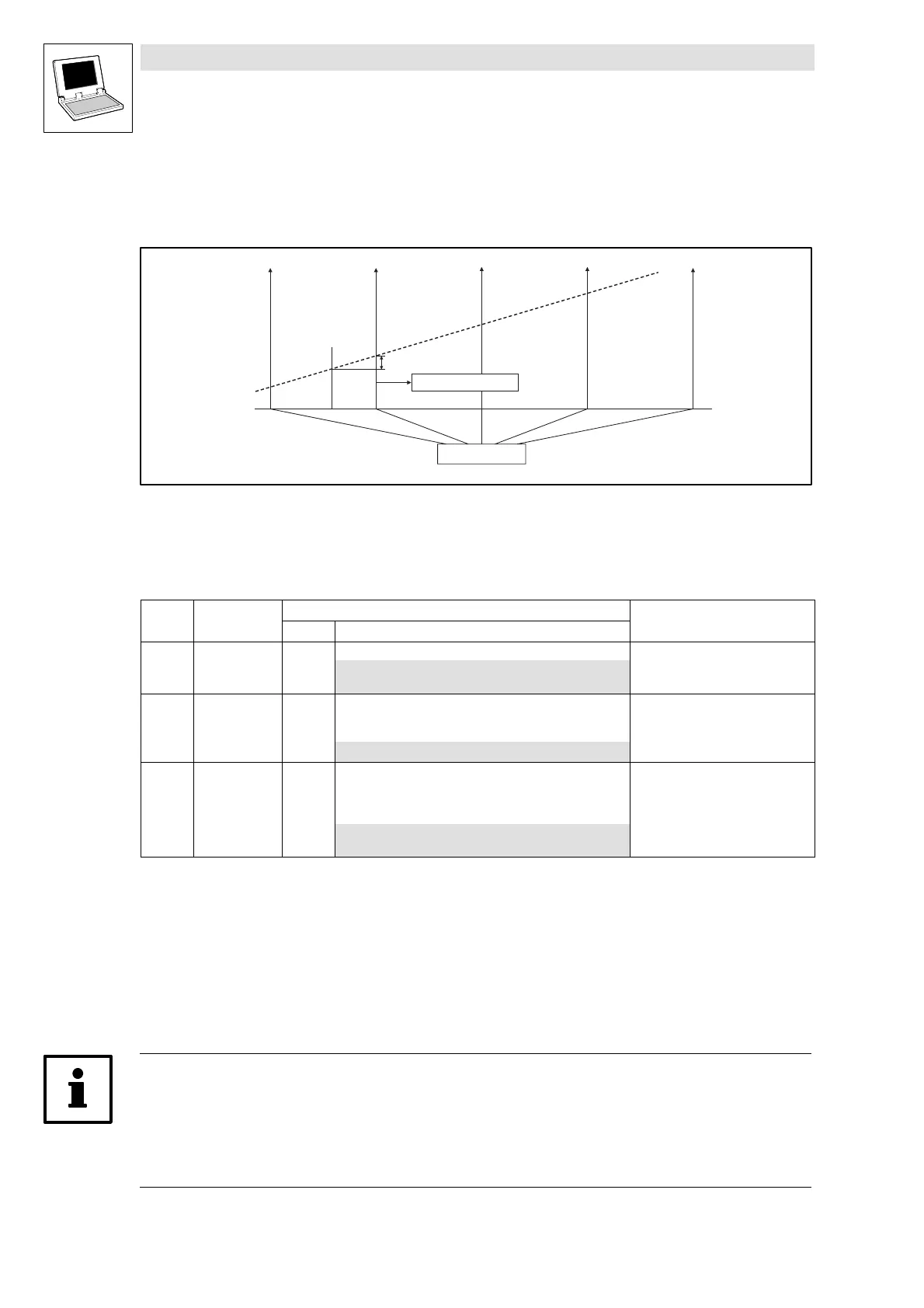
2.8.1.2 Touch probe (TP)
Process: The current angle value (digital frequency input value) is stored by a quick interrupt in the
operating system when a signal change occurs at the TP activating input (e.g. X5/E5).
DFIN_dnIncLastScan_p
TP
j
Fig. 2-17 Function diagram of a TP
Time-equidistant start of an interval-task
ϕ Phase-angle signal
Touch probe configuration
Code LCD
Possible settings
Info
Lenze Selection
C0428 DFIN TP sel. 0 Touch probe selection
0 Touch probe via zero pulse
1 Touch-Probe through digital input X5/E5
C0429 TP delay 0 Touch probe delay
• Compensation of delay times of TP
signal source at X5/E5
-32767 {1 inc} 32767
C0431 DFIN TP EDGE 0 Touch probe activation
• For touch probe via digital input
X5/E5
(C0428 = 1)
0 Activation with positive signal
1 Activation with nega tive signal
Functional sequence
1. The TP is signal-controlled via the digital input X5/E5 or a zero pulse (only when the encoder is
connected).
2. If a TP has occurred,
DFIN_bTPReceived_b
is set = TRUE.
3. After the start of the task,
DFIN_dnIncLastScan_p
indicates the number of increments [inc]
counted since the TP.
4. Following,
DFIN_bTPReceived_b
= FALSE is set.
Note!
• It is necessary that all three outputs (
DFIN_nIn_v
,
DFIN_bTPReceived_b
and
DFIN_dnIncLastScan_p
) are processed in the task even if only one signal is required.
• The polarity of the digital input E5 configured under C0114/5 does not influence the signal
evaluation.
efesotomasyon.com - Lenze

 Loading...


