Installation
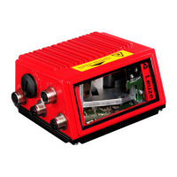
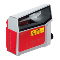
Leuze electronic BCL 8 37
TNT 35/7-24V
Switching output
The switching output connection between SW IN/OUT (pin 5) and GND (pin 3) can be acti-
vated in the scanner setup.
In the basic setting, the SW IN/OUT switching output is switched to GND (pin 3) if a code is
recognised.
Figure 6.6: Switching output BCL 8
Attention!
Do not load the respective switching output of the BCL 8 with more than 20mA at
+5 … 30VDC!
Notice!
You can configure the switching input/output according to your needs using the supplied
BCLConfig program.
+ 5 V DC
SW_IN/OUT
GND
BCL 8
GND
1
5
3
+ 5 … 30 V DC
max. 20 mA !
R
L
4.75 … 5.5 V DC
 Loading...