Electrical connection
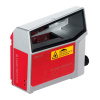
Leuze electronic BPS 307i 47
Switching input/output
The BPS is equipped with two, freely programmable, optically decoupled switching inputs/outputs, SWIO1
and SWIO2.
• The switching inputs can be used to activate various internal functions of the BPS (e.g., Measure-
ment Stop/Start, Teach Preset, Reset Preset).
• The switching outputs can be used to signal the state of the BPS and to implement external functions
independent of the superior control (e.g. position value/speed value invalid, position and speed limit
value exceeded, device error).
• The control can use switching inputs/outputs as digital I/Os.
If no internal BPS function is connected to the switching inputs/outputs, the ports can be addressed
as two inputs, two outputs or as one input and one output of a digital I/O component.
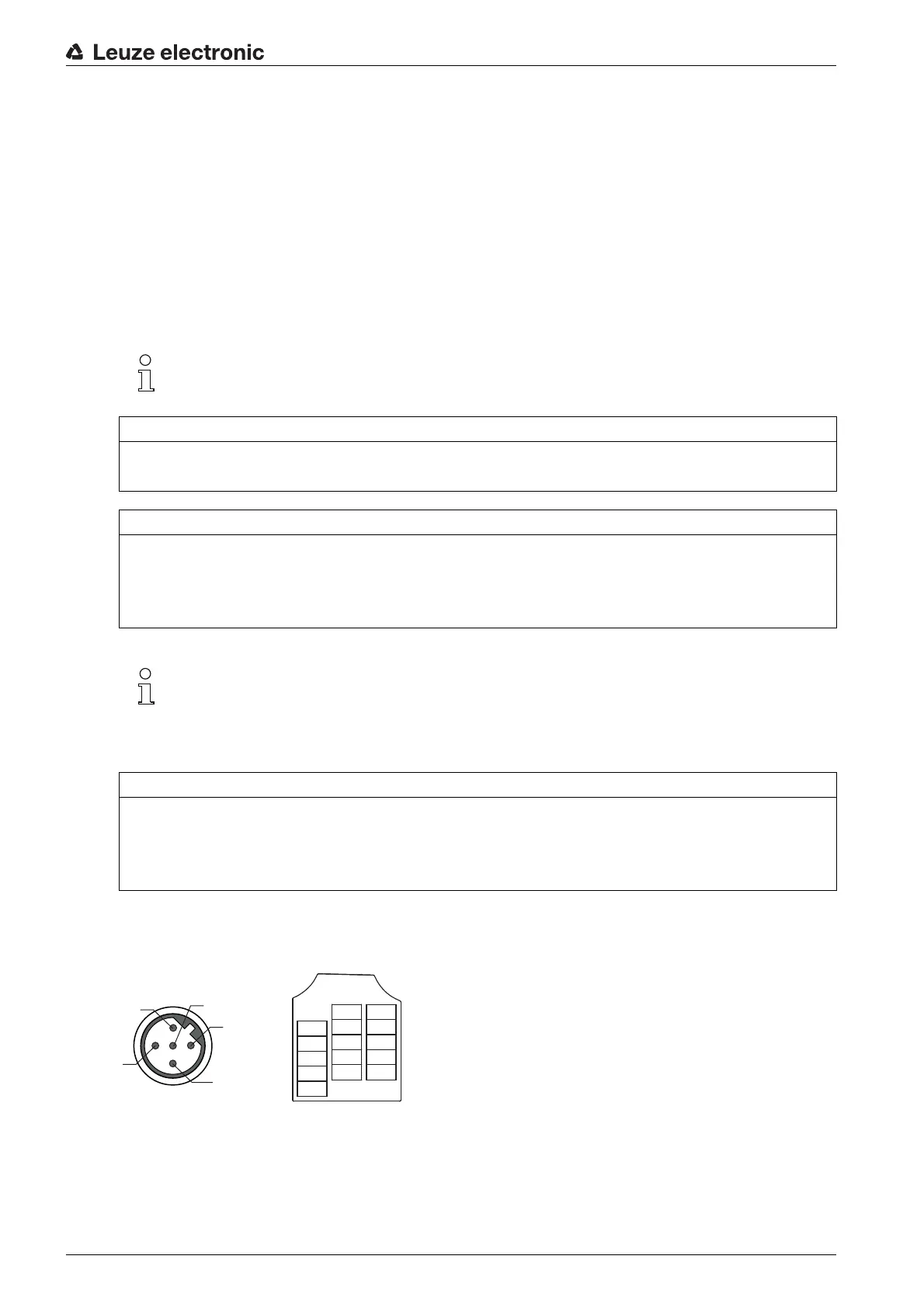
7.5.2 SSI (HOST / BUS IN)
5-pin, M12 plug (B-coded) or terminal block for connecting to an SSI interface.
Figure 7.5: SSI connection
The function as input or output is set via the webConfig configuration tool (CONFIGURATION >
DEVICE > Switching inputs/outputs, see chapter 9.3.2).
NOTICE
Maximum input current
The input current of the respective switching input is maximum 8 mA.
NOTICE
Maximum loading of the switching outputs
Do not load the respective switching output of the BPS with more than 60 mA at + 18 … 30 VDC in
normal operation.
Each configured switching output is short-circuit proof.
The two switching inputs/outputs, SWIO1 and SWIO2, are configured as follows by default:
Switching output SWIO1: Position value invalid
Switching input SWIO2: Teach Preset
NOTICE
SWIO1 and SWIO2 as switching output
At the outputs of the BPS (SWIO1 and SWIO2), no switching outputs may be connected from external
sensors/devices.
The switching output of the BPS may otherwise malfunction.