Basic configuration
Leuze electronic BPS 307i 52
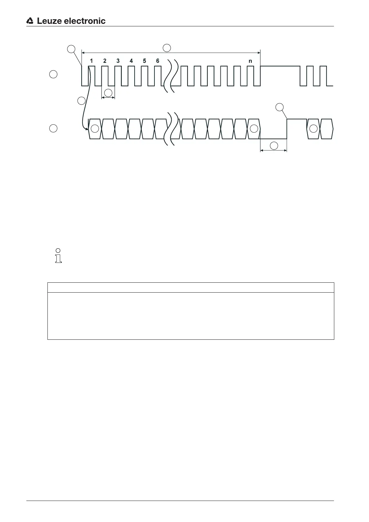
1CLOCK
2DATA
3 Clock sequence
4 First HIGH-LOW edge
5 Change LOW level to HIGH level
6 Bias level (HIGH)
7T
SSI
(1/f
SSI
)
8T
m
= 20 µs or 30 µs
9MSB
10 LSB (0)
Figure 8.1: SSI data transmission sequence diagram
Factory settings of the SSI interface parameters
• Data encoding of the measurement values:
Gray
•Sign:
binary representation
• Transmission mode: 24 measurement bits + 1 error bit
• Resolution position value: 1 mm
• Error bit: measurement error, LSB,
1
= active
• Value of the error bit:
The error bit is not included in the Gray encoding of the measurement value.
The error bit is
1
= active
• Update rate: 2 ms
• SSI master clock frequency: 80 kHz - 800 kHz
If the off-cycle of data transmission is interrupted for longer than t
m
= 20 µs or t
m
= 30 µs , a com-
pletely new transmission cycle starts on the next cycle.
If a new transmission cycle is started before time t
m
elapses, the previous value is output again.
NOTICE
Factory setting: only positive position and speed values with SSI!
In the factory setting, the SSI interface can only represent positive position and speed values.
If negative output values are ascertained due to the orientation of the BPS to the BCB or the counting
direction, the value
0
is output at the SSI interface!
In the event of a number overflow, all data bits are set to
1
.