User Manual for PuraLev
®
iF100SU
www.levitronix.com
PL-4079-00, Rev00, DCO# 21-271
Analog Input
(Current Input)
Reference
Value
(Set Flow or
Speed)
4..20 mA = 0..100% of full scale flow
4..20 mA = 0..10000 rpm
Speed limit = 9000 rpm
Cutt-off speed = 0 rpm
For Flow Control mode.
For Speed Control Mode.
450 Ohm shunt input, no galvanic isolation.
The designation of the analog inputs can be
changed with Levitronix
®
Service Software.
Analog Input
(Voltage Input)
Configurable as
setpoint input
Analog voltage input: 0 – 10V
(7.9 kOhm, no galvanic isolation).
Note: Max. input voltage of 11 V shall not be
exceeded.
The designation of the analog inputs can be
changed with Levitronix
®
Service Software.
Analog Output
(Voltage Output)
0..10 V = 0..100% of full scale flow
Direct connection, no protection. Galvanic
isolation on user side is required. GND is
reference.
The configuration of the analog output can be
changed with Levitronix
®
Service Software.
Reference for Aout1, Dout1, Dout2 and Pout.
Closed circuit active, pump running
Open circuit not active, system off or error
Open drain, max. 24V, 100mA
This signal indicates the state of the pump
system. If not active, pump is either in “Off” or
in “Error” state.
The configuration of the digital outputs can be
changed with Levitronix
®
Service Software.
Closed circuit active, measurement o.k.
Open circuit not active, measure. error
Slow blinking (2 Hz) Zero Adjust error
Fast blinking (10 Hz) Zero Ad. in progress
Open drain, max. 24V, 100mA
The configuration of the digital outputs can be
changed with Levitronix
®
Service Software.
5-24 V active
0 V not active
Galvanic separation with optocoupler and
2.2 k input resistance.
The “Enable” signal switches the pump
system on and off. Resets pump from error
state with 300-700ms pulse.
Galvanic separation with optocoupler and
2.2 k input resistance.
Triggers a Zero Adjust of the flow sensor.
Duration of Zero Adjust process is about 30
seconds.
Reference to Din1 and Din2.
24VDC ±10%, 200 mA
(Max. current is together with Pout of
Fieldbus OUT connector in Table 13)
For supply of external devices (displays etc.).
Internally protected.
Reference is GND.
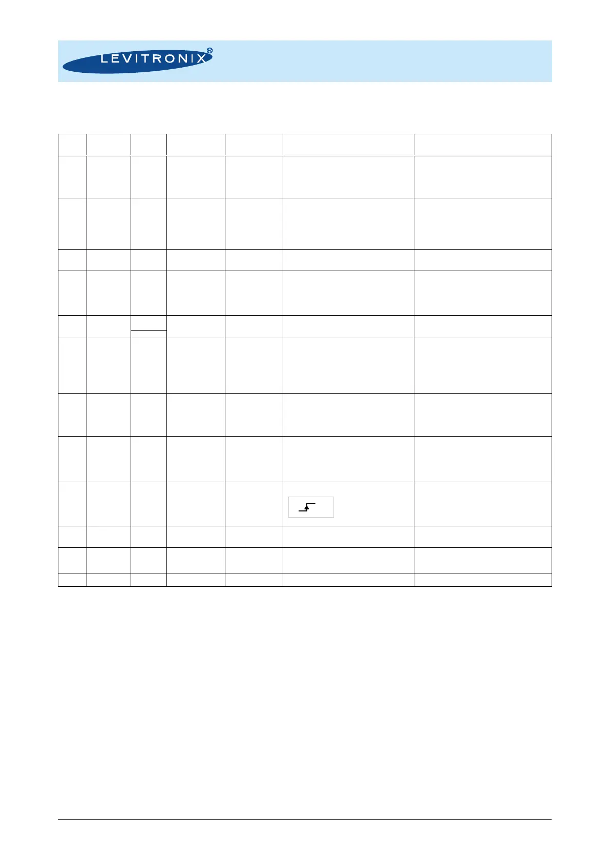
Table 14: PLC connector of EasyConnect driver
Note 1: Screw type connector pin out and wires of compatible cables: ICS-2.1-xx Note 2: Designations are for standard firmware.
 Loading...