Description
12 300855170_002_C8 - 08/2021 - © Leybold
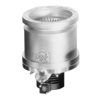
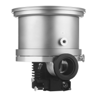
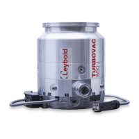
TURBOVAC 850 i(X) 950 i(X) 1350 i 1450 i
Weight ISO-K / ISO-F / CF kg
14.6 / − /
19.6
15.4 / − /
21.7
23.5 / 24.3 /
−
24.4 / 25.5 /
−
Recommended forevacuum pumps ECODRY 65 plus. TRIVAC D 65 B.
SCROLLVAC 7 plus. DIVAC 3.8 HV3
Noise level
with convection or water cooling
with radial air cooler
dB(A)
< 40
< 55
< 40
< 55
< 44
−
< 44
−
Max. bake-out temperature of the CF version, at
the high-vacuum flange, water cooled
°C 100
Max. rel. air humidity
approx. 85%
(non-condensing)
Purge gas flow
mbar · I · s
-1
sccm
0.4
24
Purge gas connection
G 1/8"
Venting connection
G 1/8“
1.3.1 Technical data for the integrated drive electronics
TURBOVAC i TURBOVAC iX
Drive electronics Drive electronics and vacuum
system control unit
Supply voltage
48 V DC +5 % / -10 % 48 V DC +5 % / -10 %
Max. current consumption
11 A (default), 13 A (max.)
at 48 V DC
11 A (default), 13 A (max.)
at 48 V DC
Max. power consumption
TURBOVAC 850/950 i
TURBOVAC 1350/1450 i
500 W (default), 600 W (max.)
600 W (default), 800 W (max.)
500 W (default), 600 W (max.)
Interfaces see ordering data see ordering data
Residual ripple < 3 % < 3 %
Max. length of the DC cable
(for variants with removable front end)
0,5 m –
Max. contact rating of the relays 48 V, 0.5 A
24 V, 1.0 A
48 V, 0.5 A
24 V, 1.0 A
Overvoltage category
II II
Contamination grade 2 2
Accessory connections 1 pc. M8 connector, 24 V DC 3 pcs M8 connector, 24 V DC
Maximum load rating for the 24 V DC outputs
(powering accessories, e.g. cooling unit or valves)
24 V, max. 18 W 24 V, 12 W
Vacuum gauge head connection – 15 pin Sub-D
 Loading...