Installation
37300855170_002_C8 - 08/2021 - © Leybold
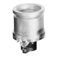
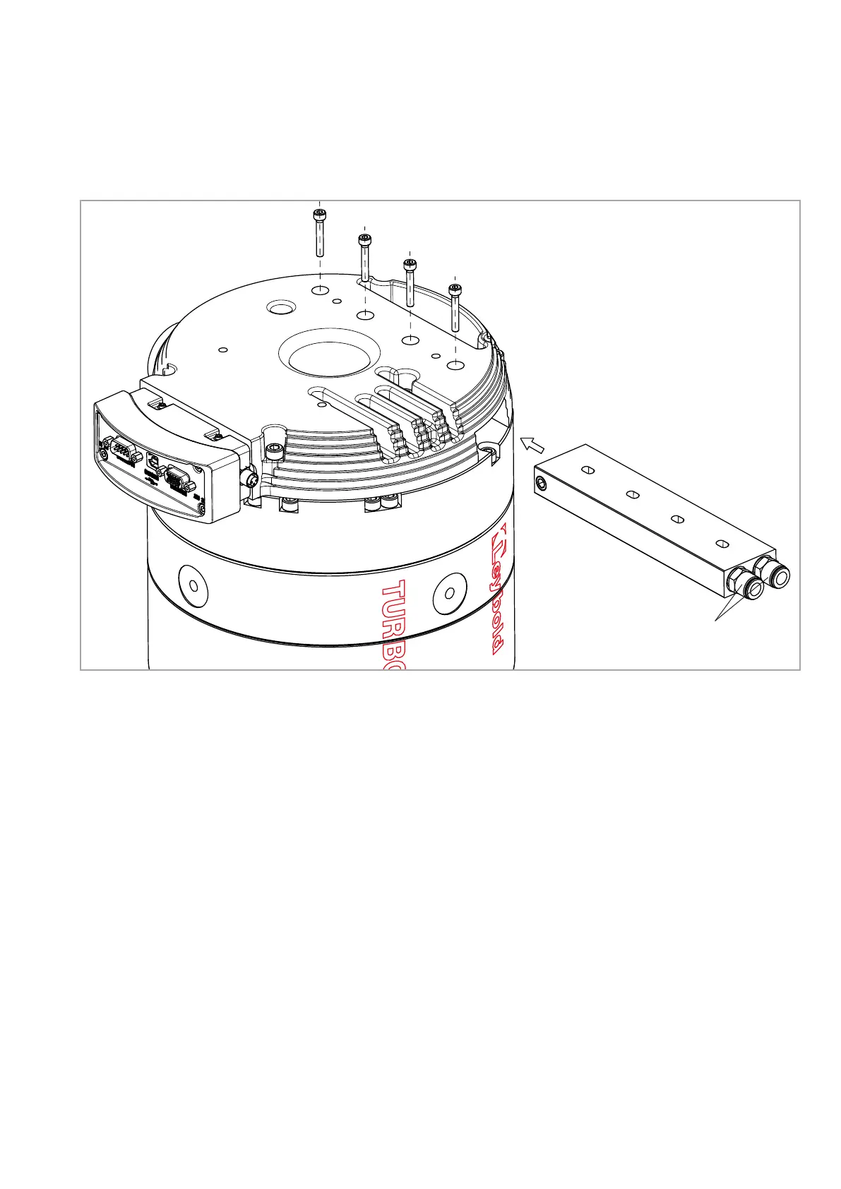
Fig. 3.8 Attaching the water cooling to the TURBOVAC 850 i and 950 i
Hose connection for
6x1 hose
3.6.2 Water cooling
TURBOVAC 850 i and 950 i
Attach the cooling water block to the TURBOVAC with 4 M4 screws, tighten-
ing torque is 3
+1
Nm. Connect the cooling water hoses.
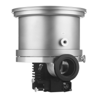
TURBOVAC 1350 i und 1450 i
The TURBOVAC have water cooling as standard. Insert the cooling water
hoses, see Fig. 3.9.
The hose connections may be unscrewed and removed, to make use of the
integrated G 1/8”-threads.
Adjust the cooling water temperature so that the formation of condensate is
avoided. With pump downtimes the cooling water has to be turned off.
When switching the cooling water supply on and off by means of an electric-
ally actuated valve, connect the valve so that it will be switched on and off
together with the pump.
 Loading...