Description
15300855170_002_C8 - 08/2021 - © Leybold
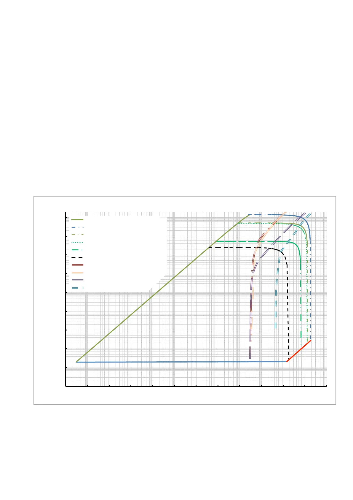
1.3.3 Operation diagrams
How to read the operating diagram for nitrogen for the
TURBOVAC850i:
With deploying a SCROLLVAC 7 plus backing pump gas flows may be trans-
ported permanently with maximum throughput quantities of
■
0.2 mbar·l/s (with convection cooling),
■
0.5 mbar·l/s (with air cooling at 40 °C), and
■
approx. 5 mbar·l/s (with cooling water at 35 °C).
These values result of the intersection between the limitations of the individu-
al cooling variant and the pumping speed of the backing pump given. As can
be seen, maximum permanent gas flows are not solely a TMP characteristic,
but are dependent from the installed backing pump, too.
Gasdurchsatz in mbarl/s
Saugleistung TURBOVAC 850i
Kühlwasser 15 °C, 100 l/h
Kühlwasser 35 °C, 50 l/h
Lüfterkühlung 24 °C
Lüfterkühlung 40 °C
Konvektion 24 °C
ECODRY 65 plus
TRIVAC D 65 B
SCROLLVAC 7 plus
DIVAC 3.8 HV3
10
-6
10
-4
10
2
10
-2
1
10
-10
10
-8
10
-6
10
-4
10
10
-2
1
10
-8
Operationsdiagramm TURBOVAC 850i für Stickstoff
Fig. 1.7 Operation diagram for TURBOVAC 850 i
Operation diagram for nitrogen for the TURBOVAC 850i
Throughput TURBOVAC 850i
Cooling water 15 °C, 100 l/h
Cooling water 35 °C, 50 l/h
Air cooling 24 °C
Air cooling 40 °C
Convection 24 °C
ECODRY 65 plus
TRIVAC D 65 B
SCROLLVAC 7 plus
DIVAC 3.8 HV3
Gas throughput in mbar·l/s
Pressure in mbar
 Loading...