31
GENERAL INFORMATION
ENGLISH
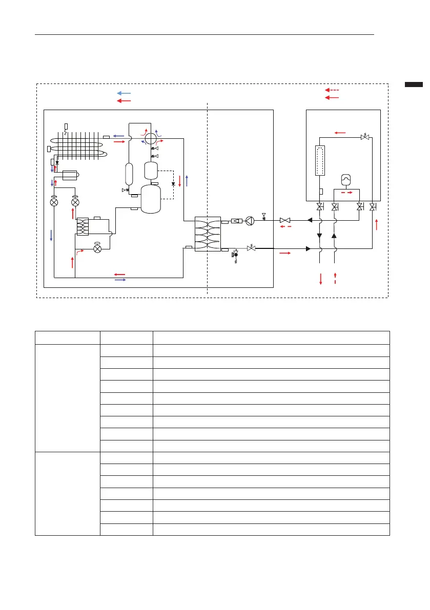
Cycle Diagram
Description
: Heating inlet
: Heating outlet
: Cooling
: Heating
Accumulator
4 Way V/V
EEV1
EEV2
EEV3
IHEX
PHEX
Air Vent
Air Vent
Water
Out
Water
In
Safety V/V
Expansion
Vessel
Shut off
V/V
S10
S3
S7
S8
S5
S2
S1
S4
S11
S12
S6
HP
LP
S17
S19
<Outdoor Unit> <Indoor Unit>
<Water Side>
<Refrigerant Side>
S13
Heat Sink
Check V/V
Check V/V
Electric Heater
Pressure
Sensor
Pressure
Sensor
Pressure
Switch
Oil
Seperator
INV
Comp
Flow
Sensor
Water
Pump
Pressure
Sensor
Strainer
Accessory
Category Symbol Meaning
Refrigerant side
S1 Outdoor-HEX gas temp. sensor
S2 Outdoor-HEX middle temp. sensor
S3 Compressor discharge temp. sensor
S4 Compressor suction pipe temp. sensor
S5 Outdoor-HEX temp. sensor
S6 Outdoor air temp. sensor
S7 Compressor-injection pipe IN temp. sensor
S8 Compressor-injection pipe OUT temp. sensor
S10 PHEX liquid temp. sensor
Water Side
S11 Inlet water temp. sensor
S12 Outlet water temp. sensor
S13 Electric backup heater outlet temp. sensor
S17 Flow sensor
S19 Water pressure sensor
LP Low pressure sensor
HP High pressure sensor
 Loading...