55
ELECTRICAL WIRING
ENGLISH
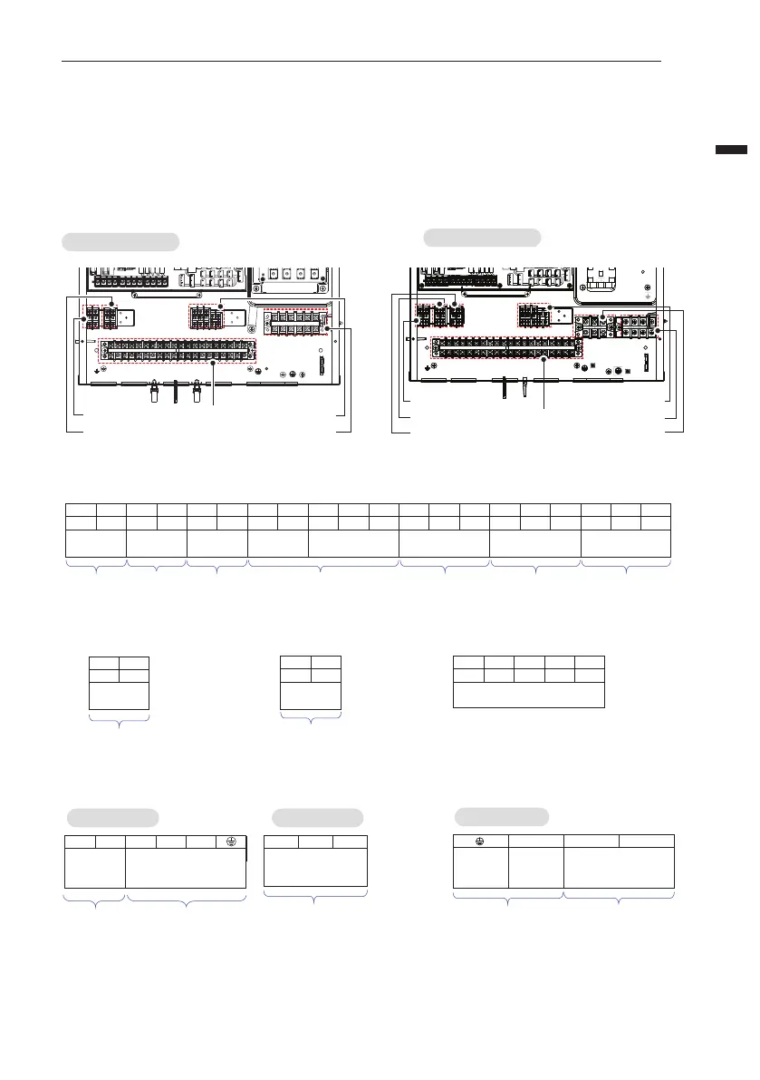
Terminal Block Information
Symbols used below pictures are as follows :
- L, L1, L2 : Live (230 V AC)
- N : Neutral (230 V AC)
- BR : Brown, WH : White, BL : Blue, BK : Black
Terminal Block 4
Terminal Block 2
Terminal Block 1
Terminal Block 5
Terminal Block 3
Terminal Block 4
Terminal Block 1
Terminal Block 5
Terminal Block 6
Terminal Block 2
Terminal Block 3
Terminal Block 7
1 Phase(Ø)
3 Phase(Ø)
Terminal Block 1
WATER
TANK
HEATER
WATER
PUMP
(B)
MIX PUMP MIX VALVE
3WAY VALVE
(A)
2WAY VALVE
(A)
POWER SUPPLY
(1Ø, 220-240 V, 50 Hz
L N L N L N L N L1 L2 N L L1 N L1 L2 N L N
1 3 4 5 6 7 8 9 10 11 12 13 14 15 16 17 18 19 202
WATER
PUMP
(C)
Power supply for
Indoor unit
Power supply for
2nd circuit heating
kit
Energizing water
pump for solar
thermal system
Turn on or
off booster
heater
Energizing water
pump for
DHW-recirculation
Closing other
circuits during
cooling operation
Water flow switching
between space heating
and DHW tank heating
Terminal Block 3
THERMOSTAT
(Default : 230 V AC)
L N L1 L2 L3
23 24 25 26 27
Terminal Block 2
3rd PARTY
CONTROLLER
(5V DC)
AB
21 22
Connection for 3rd party
controller or Modbus RTU or
Metering module (5 V DC)
Terminal Block 4
OUTDOOR UNIT
AB
28 29
Connection for
communication
Terminal Block 6
3 Phase(Ø)
External electric power
supply for
backup heater
Connecting external
electric power supply
for backup heater
POWER
SUPPLY
EARTH
TO ELB FOR
DHW TANK E/HEATER
LN
Terminal Block 5
1 Phase(Ø) 3 Phase(Ø)
TO ELB FOR
DHW TANK
E/HEATER
POWER SUPPLY
(1 Ø, 220-240 V, 50 Hz)
External electric
power supply for
booster heater
External electric power
supply for backup heater
1 (L) 2 (N) 3 (L) 4 (N)
Connecting external
electric power supply
for backup heater
POWER SUPPLY
(3 Ø, 380-415 V, 50 Hz)
RST
 Loading...