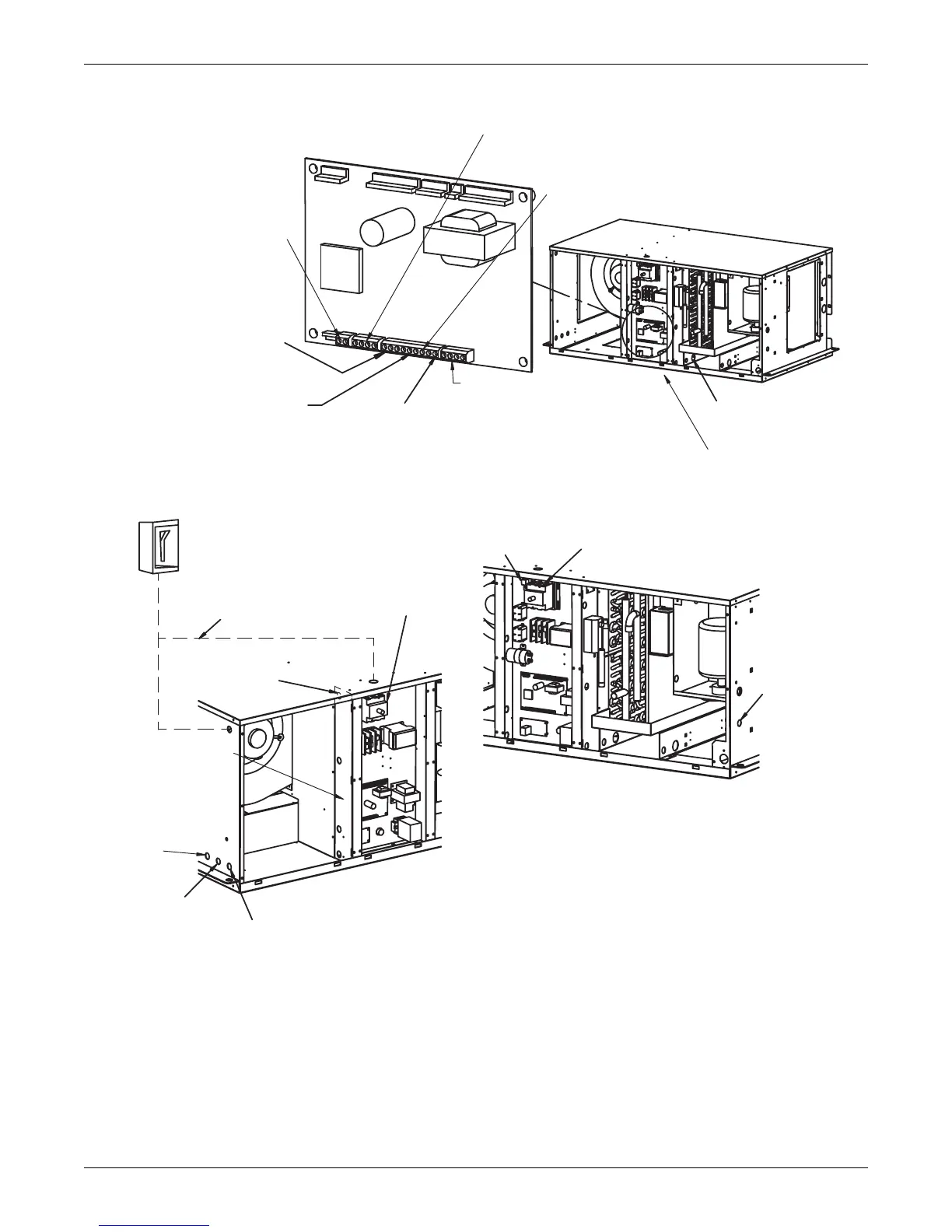
Remote Control Panel Connection to TB3-1,2,3,4 connected with field-supplied
thermostat wire (22ga., shielded/ jacketed: available from Emerson or others).
Unit Control Board terminals marked GND, +5V, T-, T+ must be connected to
corresponding terminals on Remote Control Wall Box.
Common alarm connection. Field-supplied 24V
Class 2 wiring to common alarm conn TB1-6 and TB1-7
Entrance for customer
low-voltage connections.
Remote Humidifier Contact
Field-Supplied 24V class 2
wiring to terminals 11 & 12,
located in field wire
compartment
Site monitoring connection. Terminals
TB4-1(+) TB4-2(-) are for connection
of a 2 wire. twisted pair, communication
cable (available from Emerson or others)
to optional Liebert SiteScan
Customer remote alarm connection
field-supplied 24V. Class 2 wiring
to conn TB1-1, TB1-2 & TB1-3
Remote unit shutdown. Replace existing
jumper between Terminals TB1-4 & TB1-5
with normally closed switch having a
minimum 75VA rating. Use field-supplied
24V Class 1 wire.
Optional condensate
pump aux float switch
connection to term
TB1-8 & TB1-9
Field-supplied unit disconnect
switch when factory unit disconnect
switch is not supplied
Factory-installed
disconnect switch
Electric service not by Emerson
Entrance for Customer
High-Voltage Connections
Entrance for Customer
Low-Voltage Connections
Drycooler/Circulating pump
control circuit TB70-71.
Optional w/Econ-O-Cycle
models. Use field-supplied
24V Class 2 wire.
Field-supplied,
field-wired thermostat
wire to remote
wall box
Field-supplied 24V (NEC Class 2 wiring) to
condensing module. (if applicable)
NOTES:
1.Refer to specification sheet for full load amp and wire size amp ratings.
2.Control voltage wiring must be a minimum of 16ga. (1.3mm) for up to
75' (23m) or not to exceed 1 volt drop in control line
DPN000195
Rev. 2
Electrical entrance for
optional condensate
pump
High-Voltage Power Connections. Electric
service connection terminals
Earth ground connection
Connection terminal for field-
supplied earth grounding wire
Heat rejection connection. Field-supplied
24V NEC class 2 wiring. See note 2.
For remote air cooled units from
terminals TB2-1, 2, 3 & 4 in the
Fan/Coil module to wires 1, 2, 3 & 4
in the condensing module
1. 24V GND
2. 24V Supply
3. High Pressure Alarm (OPT)
4. Hot Gas Bypass Connection