Microprocessor Control
Liebert
®
Mini-Mate2
™
52
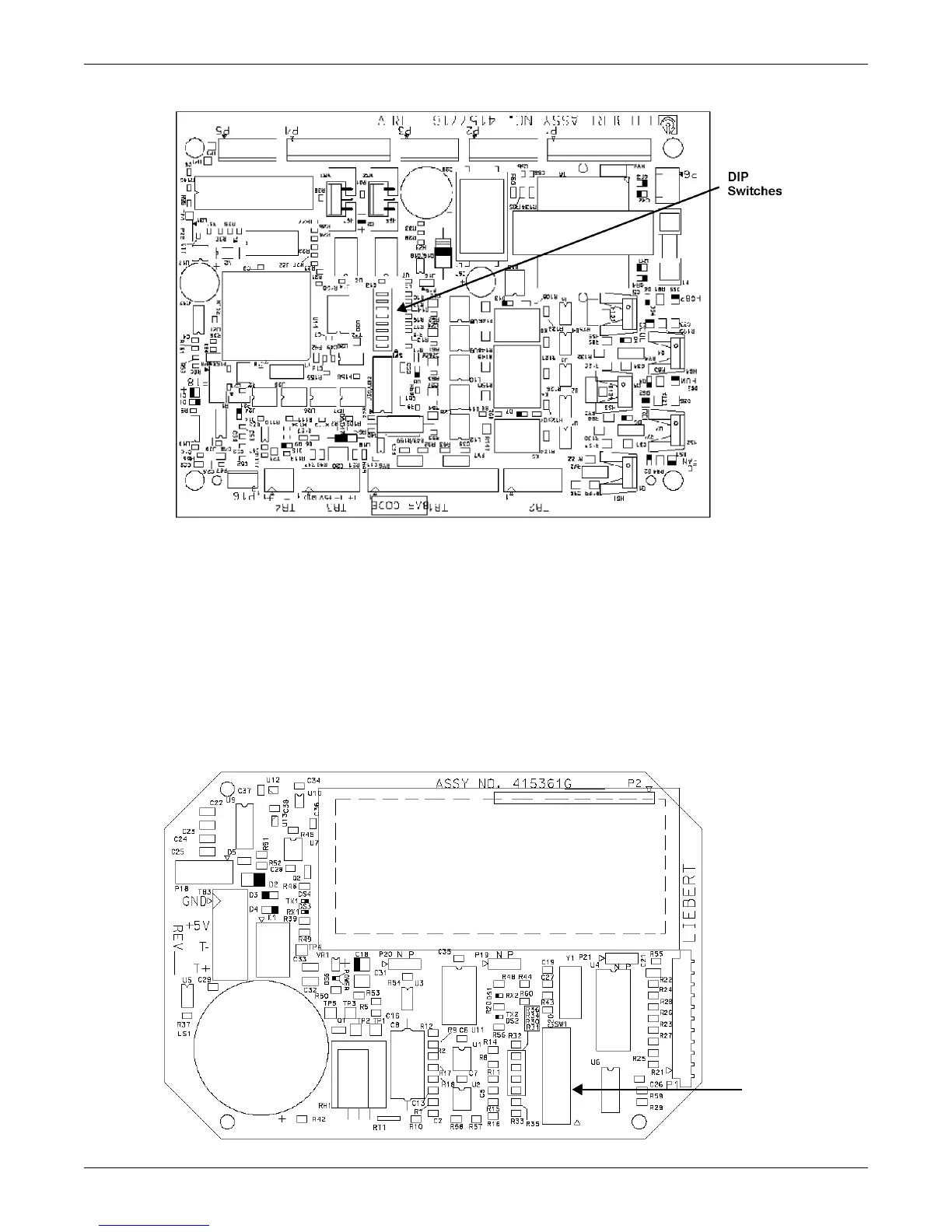
Figure 28 Control board (inside evaporator)
Figure 29 Wall box board
TB2-4 Hot Gas Bypass TB1-3 Customer Alarm Connection #2
TB2-3 High Head Alarm Connection TB1-2 Customer Alarm Connection # 1
TB2-2 Heat Rejection TB1-1 Customer Alarm Connection (Common)
TB2-1 Heat Rejection TB3-4 Connection to TB3 Pin 4 of wall box
TB1-9 Condensate Pump Aux Alarm TB3-3 Connection to TB3 Pin 3 of wall box
TB1-8 Condensate Pump Aux Alarm TB3-2 Connection to TB3 Pin 2 wall box
TB1-7 Common Alarm Connection TB3-1 Connection to TB3 Pin 1 of wall box
TB1-6 Common Alarm Connection TB4-2 Site Monitoring Connection (-)
TB1-5 Remote Shutdown TB4-1 Site Monitoring Connection (+)
TB1-4 Remote Shutdown P16 Remote Sensor Connection