Troubleshooting
Liebert
®
Mini-Mate2
™
70
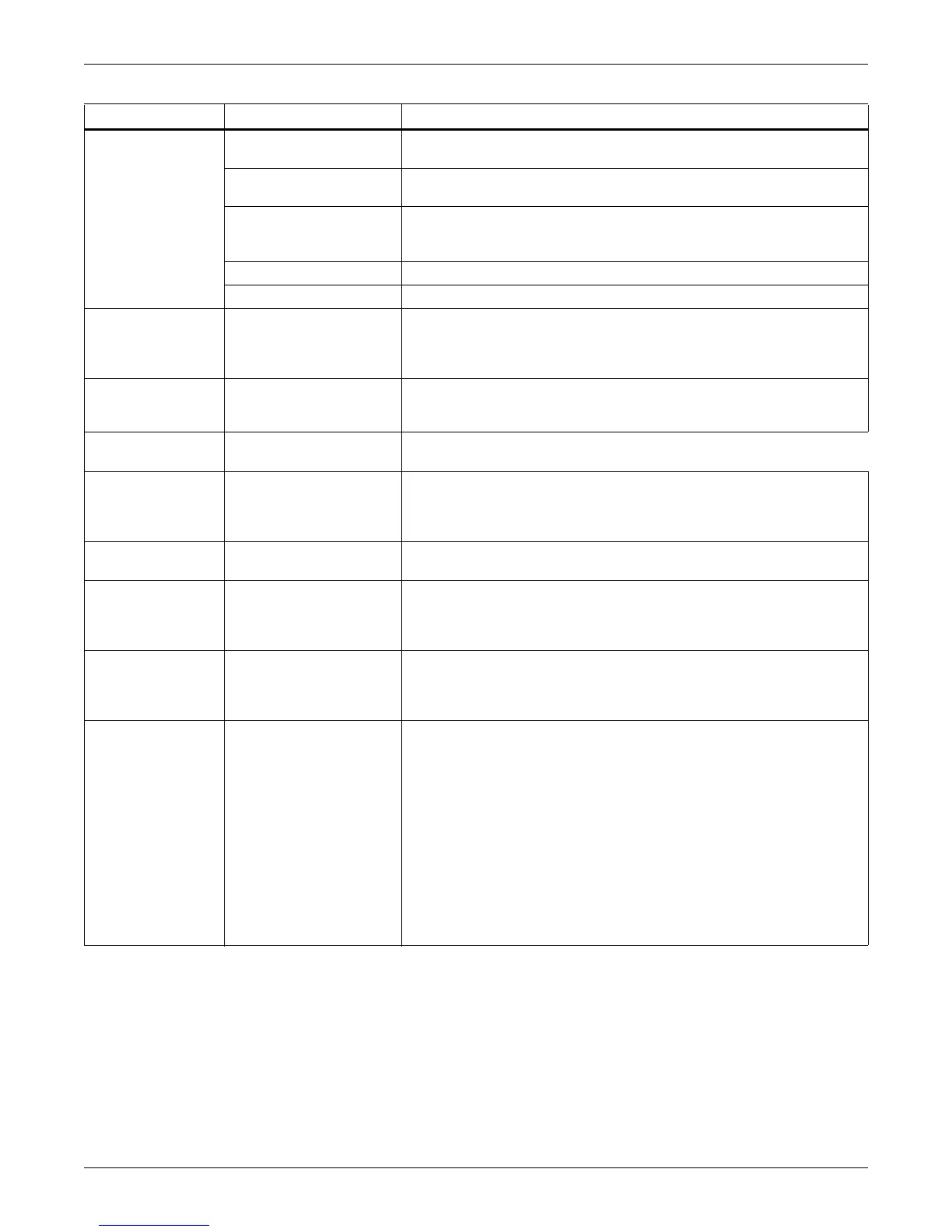
Reheat will not
operate
DIP switch not set to
enable reheat option
See DIP switch settings Table 30
“HEAT” not displayed at
the control panel
Increase temperature set point to require heating.
Reheat safety open,
defective reheat contact
or defective board
Check voltage at P2-1 and P1-9 on interface board for 24 VAC ± 2 VAC.
If voltage, check reheat contactor and reheat safety. If no voltage, check
wiring and/or replace board.
Element is burned out Turn off power. Check element continuity with Ohm meter.
GCD has tripped Replace GCD and heating element.
Fan will not operate
at low speed when
selected from
control panel.
Open wiring or failed
board
Verify “LOW FAN” is displayed at the control panel. Check for 24 VAC ±
2 VAC at terminals P3-4 and P1-9. If no voltage, check wiring and/or
replace interface board. Check fan relays.
Fan will not operate
at low speed during
dehumidification
Temperature requirement
is too high.
Verify with display. Cooling requirement overrides Dehumidification.
Cooling cycle too
short
Sensor response delay
too short
Increase sensor response delay. See 6.11 - Calibrate Sensors.
Display freezes
and control pads
do not respond
Static discharge
During period of low humidity, static electricity can cause the control
program to freeze or display incorrect information. Although this is
unlikely, the control can be reset by cycling power from the disconnect
switch.
Condensate pump
does not operate
Open or short circuit in
wiring
Find open or short circuit and repair power to pump.
Continuous
Cooling*
Failed temperature
sensor
Temperature display will indicate dashes. Check wiring from
temperature/humidity board (remote sensors) to the control board or
from control board to wall box. Replace temperature/humidity circuit
board (remote sensors) or wall box.
Continuous
Heating*
Dehumidification*
Humidification*
Shorted wiring or failed
control board
Check wiring and/or replace control board.
Display Problem Incorrect wiring
Review section 5.5.5 - Electrical Connections. Verify VDC between 5
and 6 Volts at TB-3 Pin 1 (Ground) and TB-3 Pin 2 of the control board
and wall box. If the transmit lines (TB-3 Pin 3 & 4) are not connected,
only the power LED will be lit. It will flash once every 10-12 second. If T-
is connected, but not T+, TX1 will flash approximately every 2-3 second.
And the power LED will flash once every 10-12 second. If T+ and T- are
reversed, the power LED and RX1 Will be lit and flash every 10-12
second.
NOTE: Erratic operation of the unit could occur. If no LED is lit, there is
no power or the +5VDC polarity is reversed. If any of these conditions
occur, remove power from the evaporator using the disconnect switch,
and correct wiring from the control board to the wall box.
NOTE: It may take up to 20 seconds for the display to appear on the wall
box LCD after power is applied.
Table 31 Troubleshooting (continued)
Symptom Possible Cause Check Or Remedy