Rev: 06.14.2016
Page 17
IN-WALL® Slide-out Service Manual
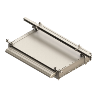
Fig. 33
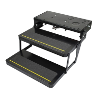
Fig. 34
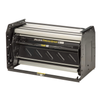
Fig. 35
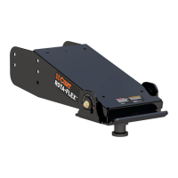
Fig. 36
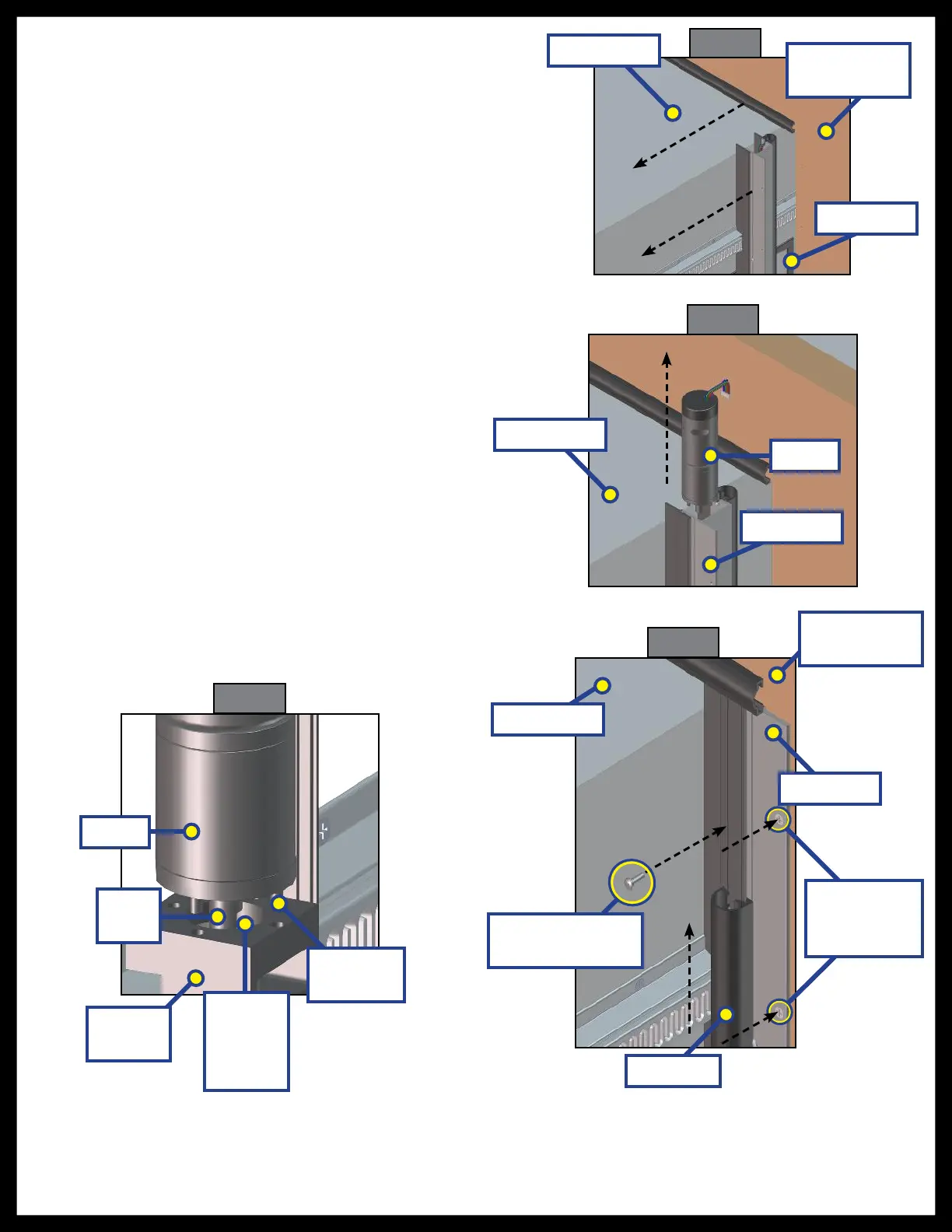
7. From the inside of the unit, push the slide-out
out until the top of the H-column is accessible
(Fig. 33).
8. Pull the motor up and out of the H-column
(Fig. 34).
9. Place new motor into the H-column, making
sure that the wiring is facing the back of the
H-Column.
NOTE: Look into the column and note the orientation
of the coupler and set screw holes in the
bearing block. Rotate the drive shaft on
the motor to approximately align with the
coupler before sliding the new motor into
the column.
10. While applying pressure to the top of the motor,
push on the column, which will slowly rotate the
torque shaft so the coupler and torque shaft can
line up with the motor shaft. Once they are lined
up, the motor will drop into place (Fig. 35).
11. Reattach the wiring harness to the motor.
12. Push the slide-out back into place.
13. Replace all screws into the H-column to reattach
the slide-out to the unit (Fig. 36).
14. Replace the motor retention screw (Fig. 36).
15. Slide the bulb seal back up into position (Fig. 36).
16. Reseal H-column according to RV manufacturer
recommendations.
17. Re-glue wipe seal.
Motor Retention
Screw
Bulb Seal
Motor
Motor
Drive
Shaft
Bearing
Block
Coupler
(Inside
Bearing
Block)
Set Screw
Pins
Slide Room
Slide Room
Slide Room
Outside Wall
of Coach
Outside Wall
of Coach
H-Column
H-Column
H-Column
H-Column
Attachment
Screws

 Loading...