CHAPTER 1: ALARMS
QUICK LOAD SERVO 65/80
1-27
Mitsubishi Servo Amplifier Alarm List
CAUTION
• Excessive adjustment or change of parameter setting must not be made as it will make operation
instable.
POINT
Using the optional servo configuration software, you can refer to unrotated servo motor reasons, etc.
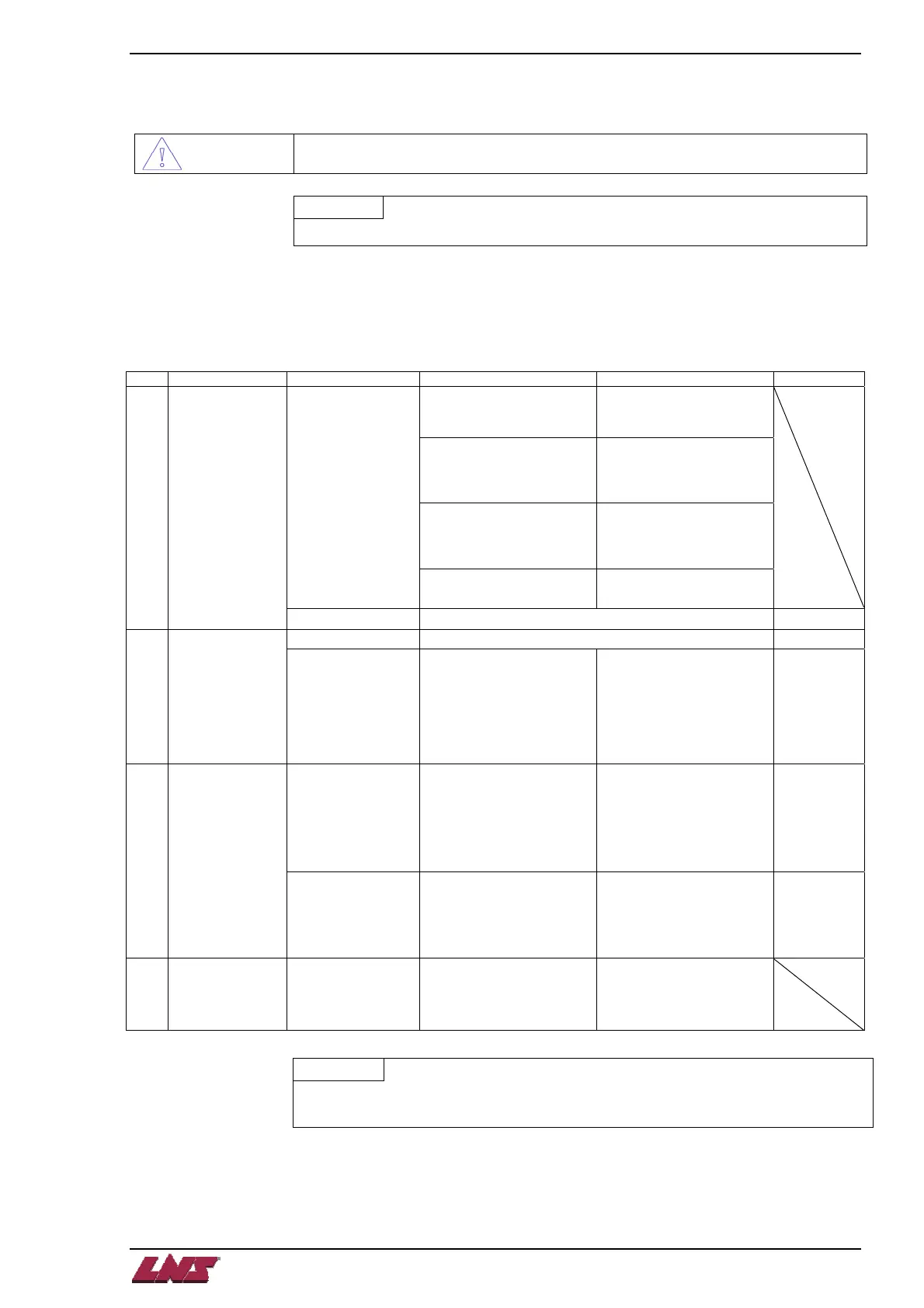
The following faults may occur at start-up. If any of such faults occurs, take the corresponding action.
Position control mode
(1) Troubleshooting
No . Start-up sequence Fault Investigation Possible cause Reference
Not improved if connectors
CN1A, CN1B, CN and CN3 2
are disconnected.
1. Power supply voltage fault
2. Servo amplifier is faulty.
Improved when connectors
CN1A and CN1B are
disconnected.
Power supply of CNP1
cabling is shorted.
Improved when connector
CN2 is disconnected.
1. Power supply of encoder
cabling is shorted.
2. Encoder is faulty.
• LED is not lit.
• LED flickers.
Improved when connector
CN3 is disconnected.
Power supply of CN3 cabling
is shorted.
1 Power on
Alarm occurs. Refer to Section Alarm and warning list and remove cause. Section 11.2
Alarm occurs. Refer to Section Alarm and warning list and remove cause. Section 11.2 2 Switch on servo-
on signal.
Servo motor shaft is
not servo-locked
(is free).
1. Check the display to see if
the servo amplifier is ready
to operate.
2. Check the external I/O
signal indication to see if the
servo-on (SON) signal is
ON.
1. Servo-on signal is not
input.
(Wiring mistake)
2. 24VDC power is not
supplied to COM.
Section 6.6
of the
Mitsubishi
Servo
Amplifier
manual
Rotation ripples
(speed fluctuations)
are large at low
speed.
Make gain adjustment in the
following procedure:
1. Increase the auto tuning
response level.
2. Repeat acceleration and
deceleration several times to
complete auto tuning.
Gain adjustment fault
Chapter 7 of
the
Mitsubishi
Servo
Amplifier
manual
3 Gain adjustment
Large load inertia
moment causes the
servo motor shaft to
oscillate side to side.
If the servo motor may be
run with safety, repeat
acceleration and
deceleration several times to
complete auto tuning.
Gain adjustment fault
Chapter 7 of
the
Mitsubishi
Servo
Amplifier
manual
4 Cyclic operation Position shift occurs Confirm the cumulative
command pulses,
cumulative
feedback pulses and actual
servo motor position.
Pulse counting error, etc.
due to noise.
When alarm or warning has occurred
POINT
• Configure up a circuit that will detect the trouble (ALM) signal and turn off the
servo-on (SON) signal at occurrence of an alarm.