18
Method 2:
- Move the back fence towards the chassis until it is not in
operation, and then secure it in that position. (Make sure
that the cutter head can rotate freely.)
- Set the front fence straight and in a position that gives you the
desired takeoff. Tighten the screws that secure the fence.
- Close the protective cover and take the steps needed for
starting the machine (see p.4).
- Start the lower cutter, both the side cutters and the feeding,
and then feed the machine with an approx. 1 meter (3.28 ft)
long test board. When the board reaches the movable cutter
(cutter 3), you stop the machine.
- Set the back fence up against the planed part of the
board.
- Check that the test board has contact with both fences, and
tighten the lock nuts of the back fence.
Make sure that all screws that hold the fences are rmly
tightened, and that the cutter head can rotate freely.
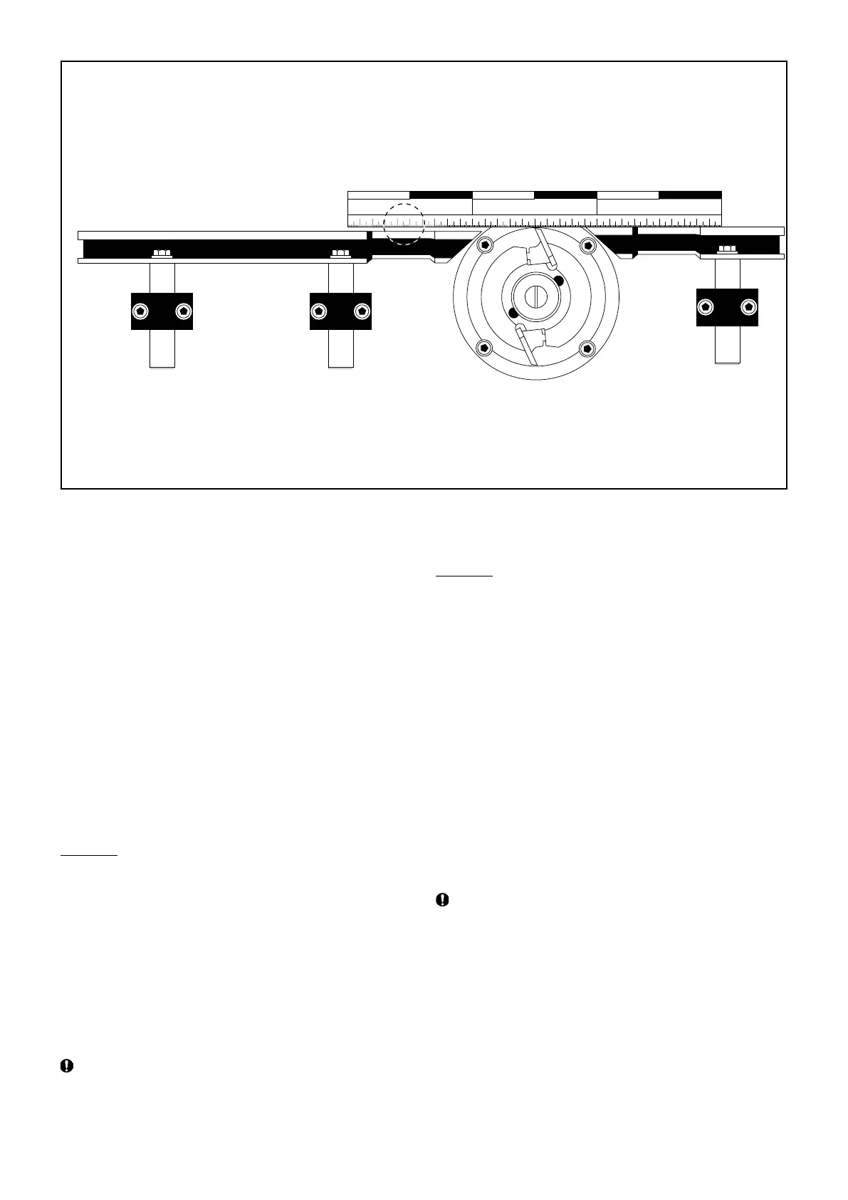
Adjusting the fences at cutter 2
The stationary cutter has two fences, the front fence (62) and the
back fence (54). The front fence decides how much the cutter
should take off, and the back fence serves as a support for the
work piece when it has passed cutter 2 and is just about to be
processed by cutter 3.
The two fences should be parallel with each other, but the front
fence should be set slightly more to the right (see the picture
above). This way, the back fence will support the work piece
when it has been processed by cutter 2 (the work piece is then
somewhat narrower).
The fences are held in place by 13 mm hexagonal screws on
the fence brackets (55) (see the picture above). The screws
that lock the fence lengthways are found in the U channel of
the fence.
Method 1:
Logosol’s setting rule (art. no. 7502-001-0405) facilitate
adjustments of the stationary cutter’s fences.
- Loosen all screws holding the fences.
- By using the magnets of the setting rule, t it to the carriage
of the movable cutter, then adjust it into the correct angle by
using its two screws. After this, the setting rule is adjusted
so that it is level with the outermost cutting diameter of the
cutter. Now the fences can be set against the setting rule.
The takeoff will be 2 mm. If you want more or less takeoff,
you can e.g. use the spacers as shims when adjusting.
Make sure that all screws that hold the fences are rmly
tightened, and that the cutter head can rotate freely.