19
Tip: If the board does not follow the fences, the cause may be
that the back fence is not on the right level with the cutter, that
the fences are not parallel to each other, or that the fences are
not positioned straight in the machine. If you have difculties in
getting the fences positioned straight in the machine, it is better
that they are angled slightly to the left, in the direction of cutter
3. Then the feed rollers will press the work piece up against the
fences. If the fences are angled slightly to the right, away from
cutter 3, the feed rollers will pull the work piece away from the
fences, which will lead to incorrect measurements and a planed
surface that is below par.
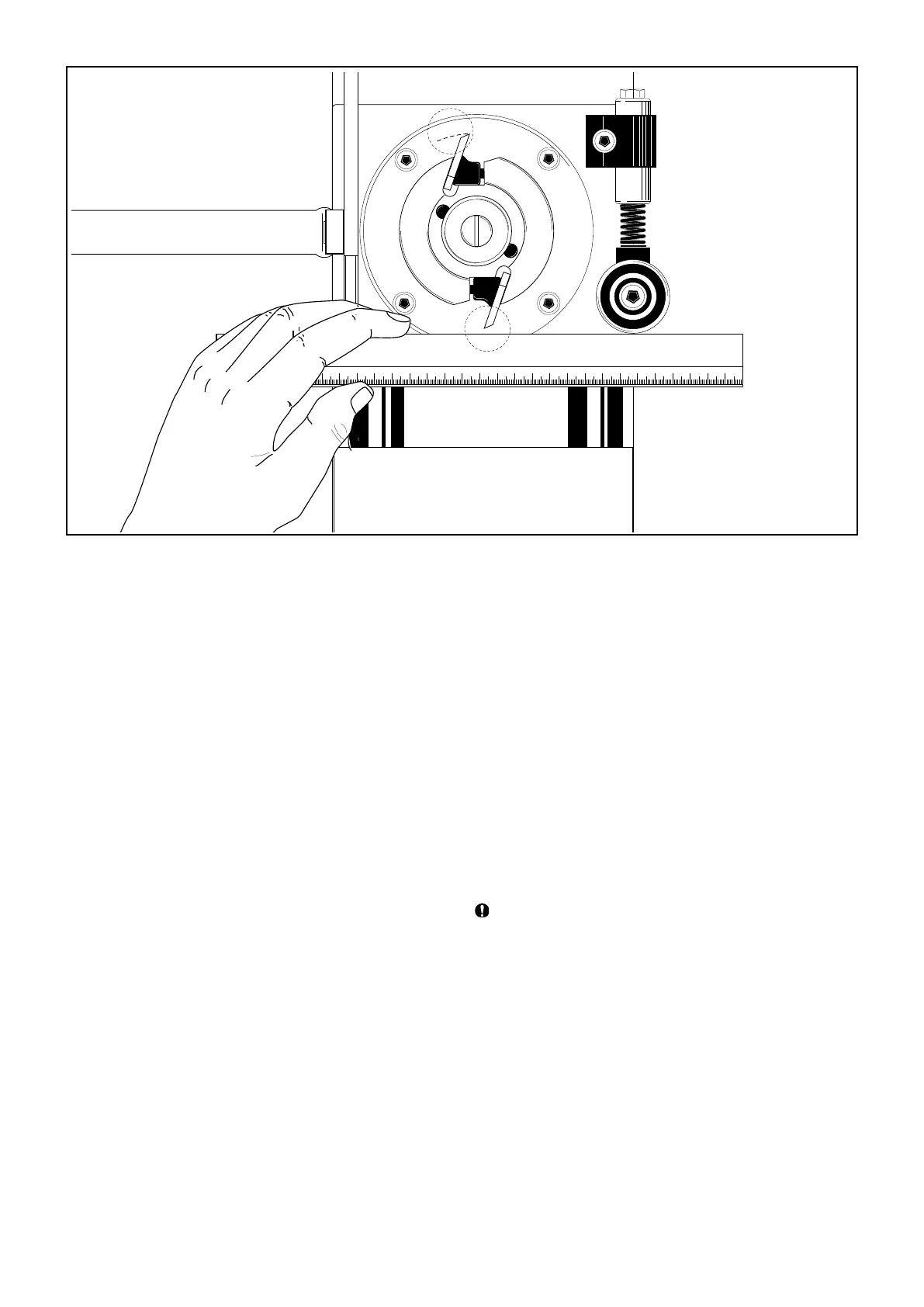
Adjusting cutter 3 (the movable cutter)
Loosen the locking handle (21), which is located on the carriage
under the machine table. Using the crank (42) at the side of
the machine, move the cutter in or out to the desired planing
width. One turn on the crank represents 4 mm (ca. 0.2”). Using
a vernier calliper, measure the distance between the cutter and
the back fence. This measurement represents the width of the
processed board. Fix the cutter in this position by tightening the
locking handle under the machine table.
Setting the pressure rollers and the chip deector at the
movable cutter
In front of the movable cutter there are two pressure rollers
(68), which press the work piece up against the fences. By
adjusting these you determine how wide a work piece the
machine can be fed with. These pressure rollers are mounted
on an aluminium L bracket (64) that is attached to the movable
cutter’s carriage, which makes them move with the cutter when
it is being adjusted.
To set the pressure rollers, you loosen the Allen screw (using
a 6 mm Allen key) that secures the L bracket on the carriage
of the movable cutter. Adjust the L bracket so that the pressure
rollers are pressed in approx. 5 mm when the work piece is fed
into the machine.
In front of the movable cutter you can mount a chip deector
(supplied) between the L bracket and its vertical screw plate.
The chip deector has oval holes, which enable the deector
to be moved in or out from the work piece. The chip deector
serves as a chip guide, but also as a fence in front of the cutter,
which lowers the risk of long splinters being produced from the
work piece, when the cutter takes off a lot of wood.
Adjust the chip deector so that it will be pressed in a couple
of millimetres by the part of the work piece that is not yet
processed.
When you are processing boards of various widths, make
sure that the chip deector does not run the risk of being
pressed in so much that it comes in contact with the cutter
knives. When the deector is pressed in, there should be a
safety margin of at least one centimetre (0.4”) between the
deector and the cutter knives.
Behind the movable cutter there is an additional pressure
roller (46), which presses the work piece up against the back
fence. Set this pressure roller so that it extends approx. 1-3 mm
(0.04-0.1”) past the cutter’s innermost cutting diameter at the
level of the pressure roller.