72 73
ENEN
Centering the brake
1. Turn the centering screw (Figure 20) in small
increments.
2. If the brake has two centering screws, adjust the
overall spring tension while centering the brake.
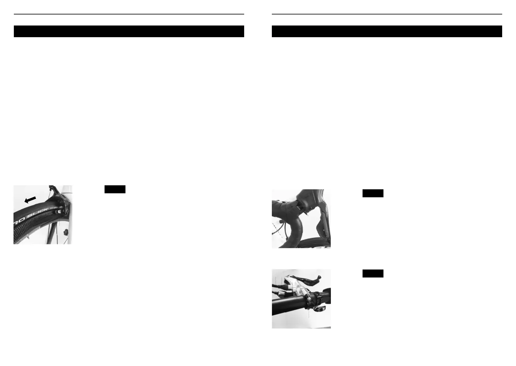
Aligning the brake pads with the wheel rim
1. Loosen the brake shoe alignment bolt
2. Align the brake pads as shown on Figure 22.
Tighten the brake shoe alignment bolt.
• Caliper : 5 to 7 N•m
3. Once you have nished, check brake function by
pulling the brake lever. Ensure the cable does not
slide in the pinch bolt, and that the brake pads are
parallel to the rim.
Disengaging the brake before removing the wheel
• Lift the quick release lever (Figure 20) on the
brake to open it. Lower it to close.
• If you have a Campagnolo system, the release
button is located on the top of the shifter. Pull the
lever slightly and press the button until it is ush with
the lever. Release the lever.
• To close the brake, reverse the procedure.
Aligning a hydraulic disc brake
1. Loosen the caliper mounting bolts (Figure 21).
2. Pull the brake lever hard and tighten the bolts to
12 N•m.
Aligning a mechanical disc brake
This procedure requires three separate steps :
A. Adjusting the clearance of the right brake pad
1. Turn the xed pad adjustment screw or bolt.
(Figure 21).
2. If you are unable to adjust the pad, follow the
instructions in section B, “adjusting the distance
between the left brake pad and the disc”, then adjust
the right hand pad.
B. Adjusting the clearance of the left brake pad
1. To increase the space between the pad and the
disc, turn the barrel adjuster clockwise. To reduce the
distance, turn the barrel adjuster counterclockwise.
• If you are unable to correctly adjust the pads,
loosen the cable pinch bolt. Retension the cable and
tighten the bolt again to between 6 and 8 N•m.
2. Once you have adjusted the brake, tighten
the lock nut to help prevent rotation of the barrel
adjuster.
C. Aligning the brake with the disc
1. Loosen the caliper mounting bolts
2. Place a business card or other slim object
between the right brake pad and the disc.
3. Pull the brake lever hard and tighten the bolts to
12 N•m.
Removing disc brake pads
1. Remove the wheel.
2. Depending on the brake model, remove the
retaining pin or screw holding the pads in place.
3. Using ngers or forceps, grasp the tab on the pad
and pull.
Fig. 22
1.Brake pad aligned
with the wheel rim
2.Pad and rim
should be parallel
3.Direction of
wheel rotation
3
1 2
Brake levers
Brake levers control the brake. The lever should be
positioned on the handlebar in such a way that you
can reach it with minimal effort and movement.
There are several types of brake levers :
• Road cycling brake levers : for racing handlebars
(Figure 23).
• MTB-type brake levers : for at or MTB handlebars
(Figure 24).
Adjusting lever position
1. Locate the lever clamping screw (Figure 23, 24).
2. Loosen the screw by two or three turns.
3. Move the lever to your preferred position.
4. Tighten the lever: MTB or road bike lever between
6 and 8 Nm.
Adjusting the lever travel
It is possible to adjust the travel of some brake
levers, meaning the distance between the lever and
the handlebar.
1. Locate the travel adjustment screw (Figure
24) and turn it. To reduce the travel, turn the
screw clockwise and to increase it, turn the screw
counterclockwise.
2. If necessary, adjust brake pad position after
adjusting the lever travel.
Changing brake cables
To change worn brake cables, refer to instructions
on page 83.
Switching brake lever controls
In some countries or for people with special needs,
brake lever control is reversed : the right lever
controls the front brake while the left lever controls
the rear brake. If you wish to set your bike up in this
conguration, you will need to disconnect the brake
cables and housings, link them to the respective
levers, and adjust the brakes again. This procedure
requires time and a clear understanding of bike
mechanics, so ask your retailer for advice.
For any other question or procedure relating to the
brakes, consult your retailer.
Fig. 23
Fig. 24
Lever clamping bolt,
road cycling lever.
1.Lever clamping
bolt
1
Lever clamping bolt,
MTB lever
1. Lever clamping
screw
4.Brake travel
adjustment screw
5.Barrel adjuster
4.Cable
4
1
2
3
 Loading...