74 75
ENEN
Wheels
Every time you replace a tire or inner tube, check
that the rim tape is correctly positioned and covers
all the spoke heads or holes to avoid puncturing.
Every month, check the wear of your tires or tubulars.
Ensure all spokes are tight and intact to avoid any
risk of the wheel bending or loosing rigidity.
Check wheel rims every month. Keep them clean to
ensure optimal brake function. If the wear markers
on the braking strip suggest the rim is worn or if the
surface is not smooth, replace the rim.
Checking the hub bearings
1. Lift the front wheel with one hand and try moving
the wheel from left to right with the other. Pay
attention to any potential movement or sound in the
bearings.
2. Spin the wheel and listen for any grinding,
squeaking or unusal noise.
3. Repeat with the rear wheel. If either or both hubs
feel loose, grinds or squeaks, a service is necessary.
Visit your retailer as servicing wheel bearings
requires specic tools and training and should only
be carried out by a professional mechanic.
Installing a wheel
The wheel (or the disc) must slot between the brake
pads and the rear wheel must be in contact with
the chain.
Several different mechanisms are used to secure a
bike to the frame. Carefully follow the instructions
applicable to the mechanism used on your bike.
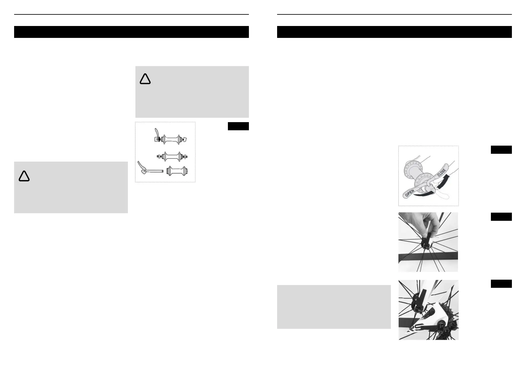
Wheel attachment mechanisms (Figure 25) :
• Traditional quick release
• Clix™ quick release
• Nutted axle
• Thru axle
Installing a wheel with a quick release axle
1. Place the axle lever in the open position (Figure
26) and place the wheel between the two fork
dropouts, which t over the skewer.
2. Bring the lever into the adjustment position, and
turn the skewer nut on the opposite side (Figure 27)
until it is nger-tight.
Fig. 25
WARNING : brake pads wear the rim. As
material is removed over time, the rim can
weaken and even break, resulting in loss of control
and a fall. Check the rims regularly and immediately
replace any worn rim.
WARNING : if the quick release system
or any other wheel attachment system is
poorly adjusted or badly closed, there could be play
in the wheel, which increases the risk of loss of
control and falling. Ensure your wheels are correctly
secured before every ride.
!
!
Wheel attachment
mechanisms
1.Traditional quick
release system
3.Nutted axle
4.Thru axle
1
3
4
3. To close the mechanism, place the lever in the
palm of your hand and close it against the fork
Figure 26. There should be some resistance as the
lever moves into the “closed” position.
• Do not tighten by twisting the lever like a wing nut
(Figure
26) as the tightness obtained in this way is
insufficient to secure the wheel.
4. If the lever closes with no resistance, it is not tight
enough either. Go back to Step 2 and tighten the
skewer nut again. For more information, read the
“torque specs” section (see below).
5. Position the levers so that they do not touch
any part of the bike, components or accessories
(such as a luggage rack or mudguards) and so not
obstable can catch the levers while riding (Figure
28).
6. Ensure the quick release mechanism is correctly
adjusted and closed by carrying out the following
checks:
• Lift the wheel off the ground and rmly tap the top
of the tire (Figure 29). The wheel must not detach,
show any play or move sideways.
• Make sure the resistance is correct when moving
the lever into the “closed” position
• Make sure the quick release lever cannot rotate
(Figure 30).
• When the quick release mechanism is correctly
closed, it is tight enough to come into contact with
the dropout surface.
If the wheel attachment test fails, adjust it again or
ask your retailer for advice or a service.
Carry out the checks again before riding.
Removing a wheel with a quick-release axle
1. Release the lever and move it into the “open”
position (Figure 26).
2. For the front wheel, loosen the skewer nut and
turn it three times.
3. Remove the wheel from the fork or seatstays.
Fig. 26
Fig. 27
Fig. 28
TORQUE SPECS : If closing the lever requires a
force greater than 200 Newton, loosen the skewer
nut slightly. If releasing the lever requires a force
inferior to 53 Newton, tighten the skewer nut slightly..
Correct lever movement
and positions
1.Unlocked (open)
2.Adjustment position
3.Locked (closed)
Front and rear lever
positions
Quick release
mechanism
1.Skewer nut
2.Lever
1
2
1
2
3
 Loading...