3. Wiring
3-4
SV-iC5
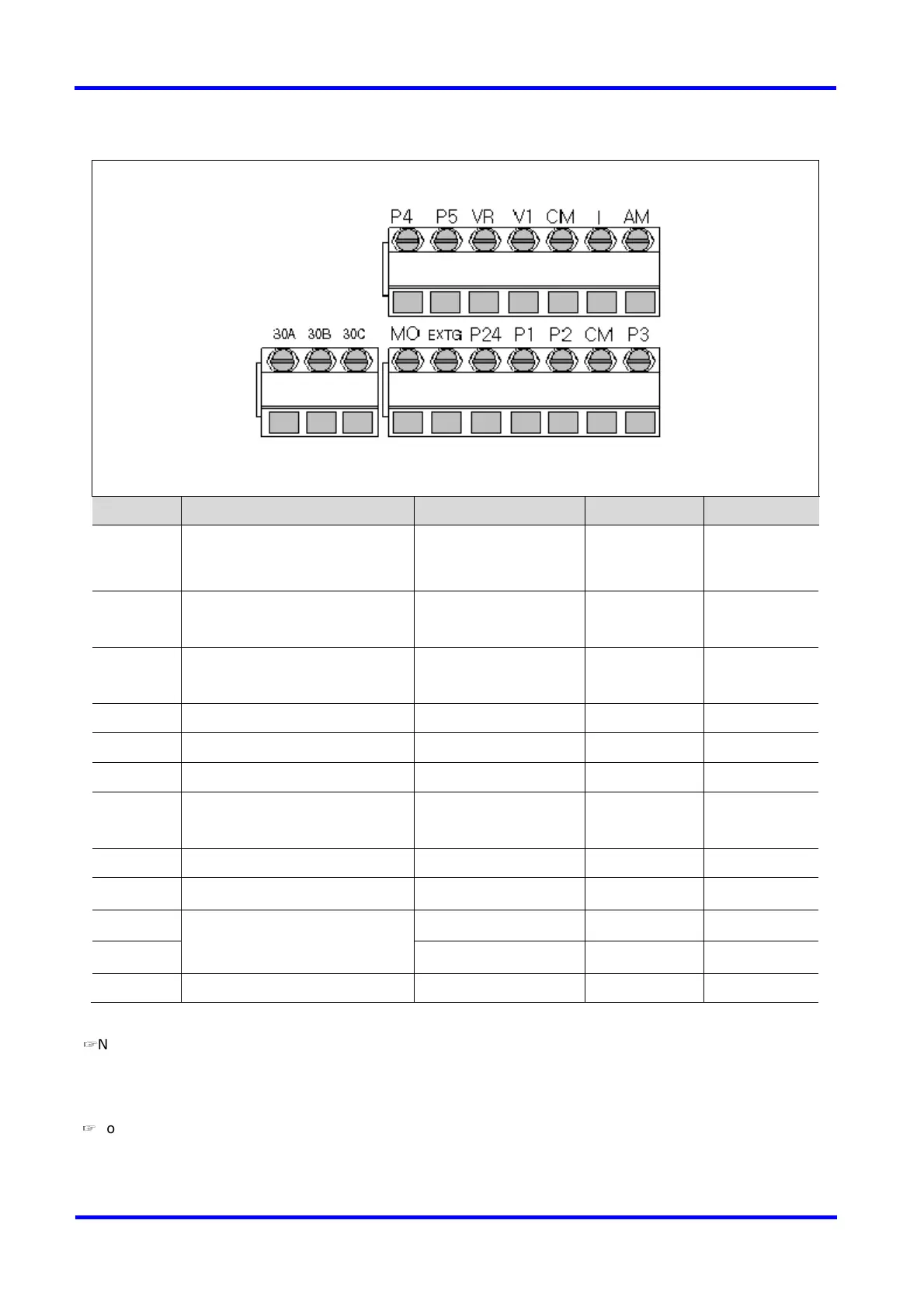
3.3 I/O terminal block specification
Terminal
Terminal Description Wire size Torque (Nm)
Note
P1/P2/P3
P4/P5
Multi-function input T/M P1-P5
22 AWG, 0.3 mm
2
0.4
CM Common Terminal for P1-P5,
AM, P24
22 AWG, 0.3 mm
2
0.4
VR 12V power supply for external
potentiometer
22 AWG, 0.3 mm
2
0.4
V1 0-10V Analog Voltage input 22 AWG, 0.3 mm
2
0.4
I 0-20mA Analog Current input 22 AWG, 0.3 mm
2
0.4
AM Multi-function Analog output 22 AWG, 0.3 mm
2
0.4
MO Multi-function open collector
output T/M
20 AWG, 0.5 mm
2
0.4
EXTG Ground T/M for MO 20 AWG, 0.5 mm
2
0.4
P24 24V Power Supply for P1-P5 20 AWG, 0.5 mm
2
0.4
30A Multi-function relay A/B
contact output
20 AWG, 0.5 mm
2
0.4
30B 20 AWG, 0.5 mm
2
0.4
30C 30A, B Common 20 AWG, 0.5 mm
2
0.4
☞
Note: Tie the control wires more than 15cm away from the control terminals. Otherwise, it interferes
front cover reinstallation.
☞
Note: When you use external power supply for multi-function input terminal (P1~P5), apply voltage
more than 12V to activate.

 Loading...


