7. Function list
7-1
SV-iC5
7. Function list
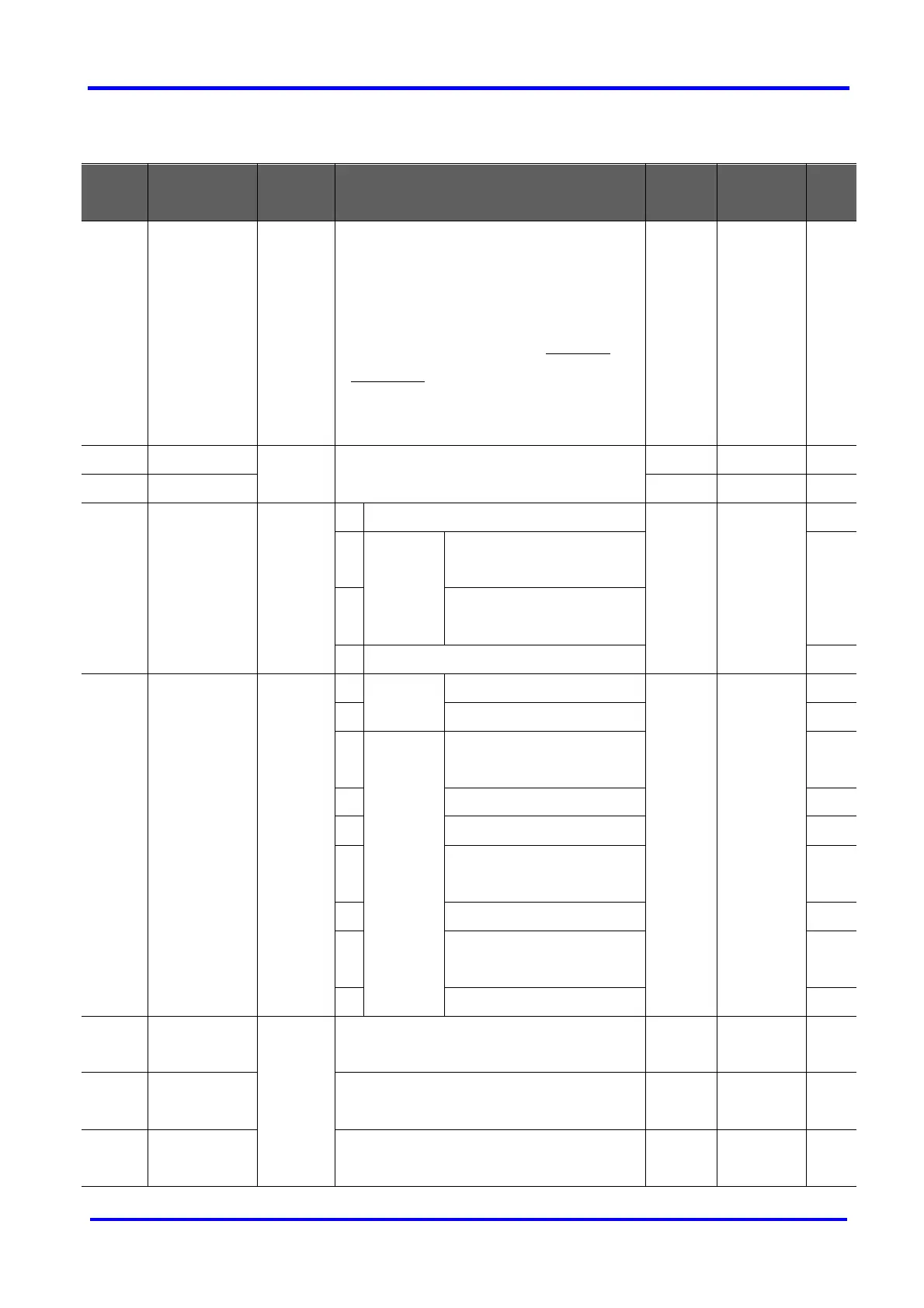
Drive Group
LED
display
Parameter
name
Min/Max
range
Description
Factory
defaults
Adjustable
during run
Page
0.0
[Frequency
command]
0/400
[Hz]
This parameter sets the frequency that the
inverter is commanded to output.
During Stop: Frequency Command
During Run: Output Frequency
During Multi-step operation: Multi-step
frequency 0.
It cannot be set greater than F21- [Max
frequency].
0.0 O 9-1
ACC [Accel time] 0/6000
[sec]
During Multi-Accel/Decel operation, this
parameter serves as Accel/Decel time 0.
5.0 O 9-10
dEC [Decel time] 10.0 O 9-10
Drv [Drive mode]
(Run/Stop
mode)
0/3 0
Run/Stop via Run/Stop key on the keypad 1 X 9-7
1
Run/Stop
via control
terminal
FX : Motor forward run
RX : Motor reverse run
9-7
2
FX : Run/Stop enable
RX : Reverse rotation select
3
Operation via Communication Option
Frq [Frequency
mode]
0/8 0
Digital
Setting via Keypad 1 0 X 9-1
1
Setting via Keypad 2 9-1
2
Analog Setting via potentiometer on
the keypad(V0)
9-2
3
Setting via V1 terminal 9-3
4
Setting via I terminal 9-3
5
Setting via potentiometer on
the keypad + I terminal
9-4
6
Setting via V1 + I terminal 9-4
7
Setting via potentiometer on
the keypad + V1 terminal
9-5
8
Modbus-RTU Communication
St1 [Multi-Step
frequency 1]
0/400
[Hz]
This parameter sets Multi-Step frequency 1
during Multi-step operation.
10.0 O 9-6
St2 [Multi-Step
frequency 2]
This parameter sets Multi-Step frequency 2
during Multi-step operation.
20.0 O 9-6
St3 [Multi-Step
frequency 3]
This parameter sets Multi-Step frequency 3
during Multi-step operation.
30.0 O 9-6

 Loading...


