10. Advanced functions
10-1
SV-iC5
10. Advanced functions
10.1 DC brake
Stop mode via DC brake
Group LED Display Parameter Name
Set
value
Min/Max
Range
Factory
Defaults
Unit
Function
group 1
F 4
[Stop mode select]
1 0/2 0
F 8
[DC Brake start frequency]
- 0/60 5.0 Hz
F 9
[DC Brake wait time]
- 0/60 0.1 sec
F10
[DC Brake voltage]
- 0/200 50 %
F11
[DC Brake time]
- 0/60 1.0 sec
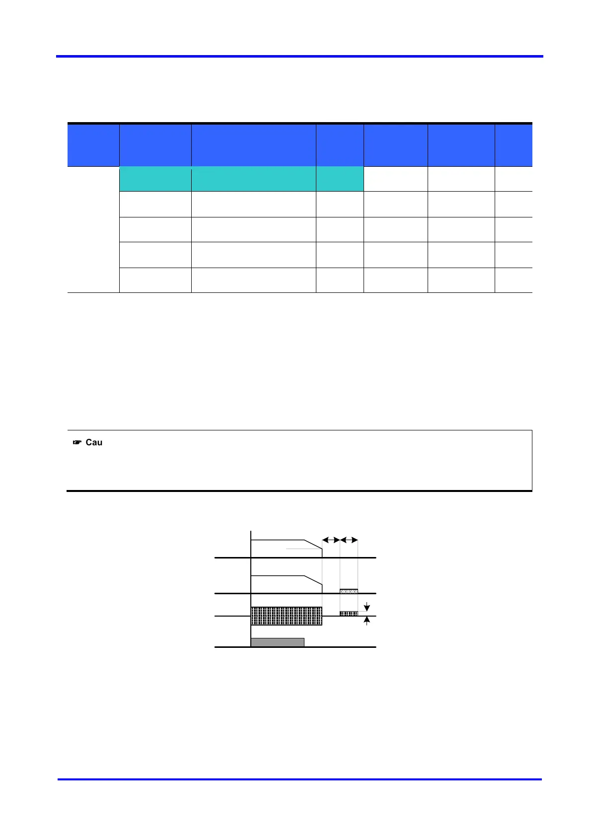
Set F4 - [Stop mode select] to 1.
F 8 : The frequency at which the DC brake will become active.
F 9 : Inverter will wait for this time after F8 - [DC Brake start frequency] before applying F10 - [DC Brake
voltage].
F10 : It sets the level as a percent of H33 – [Motor rated current].
F11 : It sets the time that F10 - [DC Brake voltage] is applied to the motor after F 9 - [DC Brake wait time].
☞
☞☞
☞
Caution:
If excessive DC Brake voltage is set or DC Brake time is set too long, it may cause motor overheating and damage
to the motor.
Setting F10 or F11 to 0 will disable DC brake.
F 9 – [DC Brake Wait time]: When load inertia is great or F 8 – [DC Brake Start Frequency] is high,
Over current trip may occur. It can be prevented via F9.
Freq.
Run
command
Voltage
Current
F 8
F9 F11
F10

 Loading...


