10. Advanced functions
10-2
SV-iC5
Starting DC brake
Group LED Display Parameter Name
Set
value
Min/Max
Range
Factory
Defaults
Unit
Function
group 1
F12 [DC Brake start voltage]
- 0/200 50 %
F13
[DC Brake start time]
- 0/60 0 sec
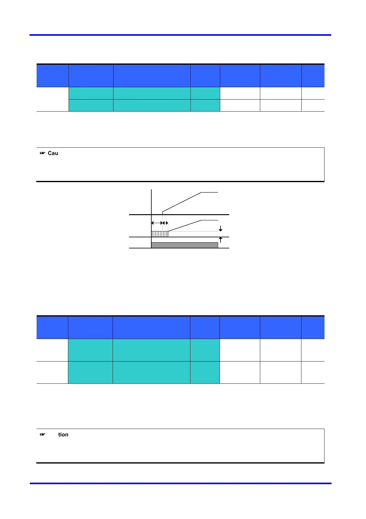
F12 : It sets the level as a percent of H33 – [Motor rated current].
F13 : Motor accelerates after DC voltage is applied for the set time.
☞
☞☞
☞
Caution :
If excessive DC Brake voltage is set or DC Brake time is set too long, it may cause motor overheating and damage
to the motor.
Setting F12 or F13 to 0 will disable Starting DC brake.
t : After F13 - [DC Brake start time], the frequency is increasing after DC voltage is applied until the
time t. In this case, DC Brake start time may be longer than the set value.
DC brake at a stop
Group LED Display Parameter Name
Set
value
Min/Max
Range
Factory
Defaults
Unit
Function
group 1
F12 [DC Brake start voltage]
- 0/200 50 %
I/O group
I22
[Multi-function input
terminal P3 define]
11 0/24 2
F12 : Set as a percent of H33 – [Motor rated current].
Select a terminal to issue a command of DC brake during stop among P1 thru P5.
If P3 terminal is set for this function, set 22 to 11 {DC brake during stop}.
☞
☞☞
☞
Caution :
If excessive DC Brake voltage is set or DC Brake time is set too long, it may cause motor overheating and damage
to the motor.
Freq.
Voltage
Run
command
F13 t
F12

 Loading...


